Table of Contents
Advertisement
Advertisement
Table of Contents

Subscribe to Our Youtube Channel
Summary of Contents for SUSS CIC1200
- Page 1 USER MANUAL Constant Intensity Controller CIC1200 Rev4.0/ 06-09 www.suss.com...
- Page 3 SUSS MicroTec assumes no responsibility for any errors, omissions, or inaccuracies. The information included in this manual is SUSS MicroTec Proprietary Information and is provided for the use of SUSS MicroTec’s customers only and cannot be used for distribution, reproduction, or sale without the express written permission of SUSS MicroTec.
- Page 4 DISCLAIMER AND PUBLISHING DETAILS DISCLAIMER...
-
Page 5: Table Of Contents
CONTENTS ONTENTS 1. Warnings and Safety Precautions ..............1 1.1. Intended Use of the CIC1200 .................1 1.2. User Requirements ..................1 1.3. Safety-Related Terms and Symbols ...............1 1.4. General Electrical Safety Precautions ............2 1.4.1. Fuse Replacement................2 1.5. Emergency Off and Safety Interlocks ..............3 1.6. - Page 6 4.10.1. Full Reset ..................27 4.11. Switching Off the Lamp ................27 5. Maintenance and Service ...................29 5.1. Maintenance ....................29 5.2. Error Messages .....................29 5.3. Service and Installation .................31 5.3.1. Installation ...................31 5.3.2. Service and Technical Assistance ............31 CIC1200 - Contents Rev4.0 06-09...
-
Page 7: Warnings And Safety Precautions
Any other use or modification of the CIC, the ignition • Warning indicates a potentially hazardous unit or the original SUSS lamp house has to be ver- situation which, if not avoided, could result in ified in advance with SUSS MicroTec Lithography. -
Page 8: General Electrical Safety Precautions
The CIC shall only be serviced by qualified SUSS technicians. There are no user related Type 3 or Type 4 tasks (referring to SEMI S22). -
Page 9: Emergency Off And Safety Interlocks
WARNINGS AND SAFETY HAZARDS 1.5. Emergency Off and Safe- ty Interlocks SUSS lamp houses and machinery (e.g. mask align- ers) are equipped with safety related interlocks ac- cording to there inherent risks. Such interlocks may consist of door locks, door switch, flow monitoring device and EMO functions. -
Page 10: Additional Warnings And Safety Precautions
Also correct lamp ori- entation is crucial (see lamp data sheets and SUSS Lamps may fail because of improper cooling, im- machine manuals for proper lamp orientation). proper settings of the power supply, usage outside the manufacturer’s guidelines, temperature shocks... - Page 11 Follow recommended standard procedures for de- contamination and cleanup. If an explosion of a hot lamp happens, the mercury OP CIC1200 E Rev4.0 06-09 Chapter 1...
-
Page 12: Eye And Skin Protection
Unprotected exposure to strong visible or infrared light may cause injuries as well. Every SUSS machine (e.g. mask aligner) is equipped with light guards, enclosing UV lamp and exposure path. The equipment shall not be operated unless all of these protective covers and devices are in place. -
Page 13: Technical Specifications Cic1200
Environmental limits: indoor use only, Temperature range: +5°C to +40°C (storage and transport condition: -10°C to +50°C) Relative humidity: max. 80% non-condensing, up to 31°C, diminishing to 50% at 40°C, • Altitude max. 2000 m OP CIC1200 E Rev4.0 06-09 Chapter 2... - Page 14 148959 Osram LH1000, LH1500 169776 Ushio USH - 1000 KS LH1000, LH1500 Other lamp types or lamp house configurations, e.g. for Near Field Holography (NFH), only by or with written consensus of SUSS MicroTec OP CIC1200E Rev4.0 06-09 Chapter 2...
-
Page 15: Program Parameters
PROGRAM PARAMETERS 3. P ROGRAM ARAMETERS for the CIC1200 for the various types of exposure lamps. (valid for software revisions > 2.10) Lamp Type [W] Lamp Life [h] Idle delay 2 time 200 Hg 1000 350 Hg 500 HgXe 500 Hg... - Page 16 PROGRAM PARAMETERS OP CIC1200E Rev4.0 06-09 Chapter 3...
-
Page 19: Operating Procedures
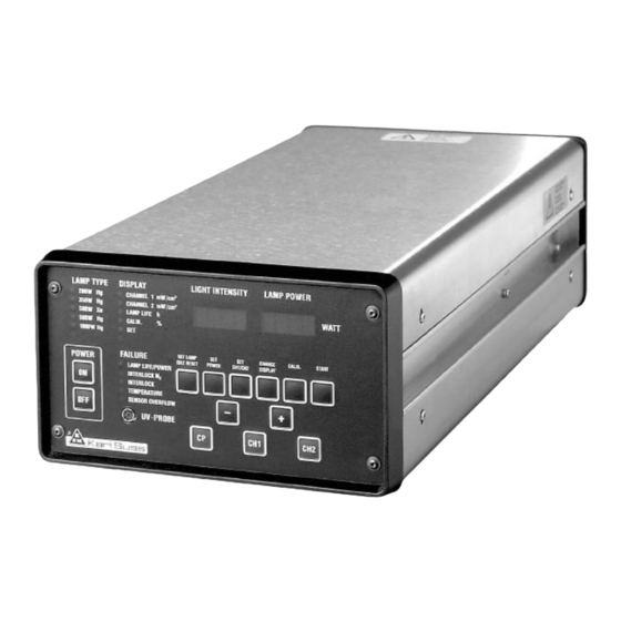
Annunciator Group LAMP TYPE Annunciator Group DISPLAY Annunciator Group FAILURE Alphanumeric Display for LIGHT INTENSITY and LAMP POWER Key Pad (see Section Key Controls) Socket for UV Probe (see Section Calibration of the CIC) OP CIC1200 E Rev4.0 06-09 Chapter 4... -
Page 20: The Annunciator Group Failure
• This LED indicates that there is an error in the PWER ERR light monitoring and control system. Contact your SUSS MicroTec Service representative. Immediate counter measures are required to (see also section 4.7.4) prevent damage; for recommended action see the introducing section of chapter 5.1. Er- ror Messages. -
Page 21: Cic1200 Rear Panel
OPERATING PROCEDURES 4.2. CIC1200 Rear Panel Main Power with Fuses (T10 A) Remote Start RS232 Control IN/OUT External Alarm Optical Sensor Lamp Interlock Lamp Cooling Interlock OP CIC1200 E Rev4.0 06-09 Chapter 4... -
Page 22: Power Supply Stand-By
Lamps driven by wrong voltage or cur- rent could not only become inoperable but may explode! The processor of the CIC1200 is constantly connect- ed to power so it monitors the crucial program steps Explosion would destroy optical com- of the exposure lamp e.g. -
Page 23: Reset Lamp Hours
The display shows: STORED and then automatically STAND BY Leave Stored Hours To leave the stored hours in memory press SET LAMP again. The display shows: NO STORE and then automatically STAND BY OP CIC1200 E Rev4.0 06-09 Chapter 4... -
Page 24: Operating Modes
OPERATING PROCEDURES 4.5. Operating Modes The three operating modes of the CIC are: CP, CH1 and CH2. Note: CP must be set also for the mask aligner mode „Constant Dose“. 4.5.1. Operating Mode CP CP stands for Constant Power. The exposure lamp is run with constant electric power: One can set the power of the exposure lamp as described in the Sec- tion 4.6.2 of the present manual. -
Page 25: Standard Operation
LIGHT INTENSITY (in CH1/CH2 mode and if the WAIT shutter is open) and POWER of the exposure lamp then (in CP mode). OP CIC1200 E Rev4.0 06-09 Chapter 4... -
Page 26: Idle Mode
Note: This section is valid ONLY for software revision < 2.00. Control Panel of the CIC1200 The exposure lamp has been ignited and after 5 min- utes (depending on the lamp type) has become op- erational. The alphanumeric display labeled LAMP POWER shows the message;... -
Page 27: Power Setting For Exposure Lamp (Cp-Mode)
Validate your entry with key SET POWER (push key for 1-2 sec). The display shows the message: STORED • and a high-pitched „beep“ is heard confirming the operator that the new parameter has been stored. OP CIC1200 E Rev4.0 06-09 Chapter 4... -
Page 28: Change Display
OPERATING PROCEDURES 4.6.4. Change Display Control Panel of the CIC1200 Actuating the key CHANGE DISPLAY you get ac- cess to the following modes of the annunciator group DISPLY listed below. The LED of the corre- sponding mode will be ON. To select another item press the key CHANGE DISPLAY. -
Page 29: Calibration Modes Of The Power Supply
CAL-UVP I 4.7.1. Basics CAL-UVP II The calibration of the power supply is done in CP • Use an external intensity meter e.g. the SUSS mode. Commence calibration only after the lamp UV1000 Intensity Meter: has become operational. • Press key CALIB for 1-2 sec. -
Page 30: Calibration Procedure With External Uv-Meter
Actuate the key START again and the display shows should be identical to those of the optical sen- the spread of measurements previously performed. sors used with the CIC controller. Therefore SUSS recommends the use of the SUSS UV in- Formula: Value - Value tensity meter UV1000. -
Page 31: Additional Functions Of Calibration Menu
Calibration Menu Use only nonconducting tools. The calibration of the digital/ analog converter S1OK, S2OK is done by SUSS Service Engineer only! If the light input is too low sometimes the value could not reach 95%. Please adjust the highest possible Press 5x CALIB. - Page 32 OPERATING PROCEDURES 4.7.4.3. UVPR To leave this menu press CALIB. Meaning: Input signal of calibrated UV-probe con- _ STO RED _ nected to socket. UV-PROBE in the front panel will be displayed. Use the same procedure for CHannel 2 (CAL2RES). 4.7.4.6.
-
Page 33: Constant Intensity Mode (Ci Mode)
The maximum output power of the 350W lamp is 400 [W] The minimum output power of the 350W lamp is 200 [W] (see Program Parameters of the CIC1200 for the various types of exposure lamps, in table 3.1) When reaching one of these max/min. values an... -
Page 34: Calibration Of The Built-In Uv Intensity Meter
UV Intensity Meter is indicated by „1“. Calibrate the built-in UV intensity meter using the tensity obtained in step 2. If necessary adjust the SUSS UV Intensity Meter (UV1000) and the UV value for the LIGHT INTENSITY with the trim- probe 405[nm] as an external reference. -
Page 35: Additional Functions
Technique for such disconnection and re-supply of the unit may depend on the specific machine type in _ RES ET? _ which the CIC is used. Press START _ RES ET _ _ STAN D-BY“ OP CIC1200 E Rev4.0 06-09 Chapter 4... - Page 36 OPERATING PROCEDURES OP CIC1200E Rev4.0 06-09 Chapter 4...
-
Page 37: Maintenance And Service
For details repeatedly causes error messages on see section "Lamp cooling" in the Installation the CIC. Manual of the respective mask aligner. • When optics or the lamp type has been changed, OP CIC1200 E Rev4.0 06-09 Chapter 5... - Page 38 NO START Current Error during IGNI- Current error during the first 10 sec of IGNITION TION (desired current +/- 5%) CIC1200 shut down CTRL ERR Power resp. Intensity Con- Deviation of desired power resp. intensity is too high troller Error for controller in CP- or CI-mode.
-
Page 39: Service And Installation
5.3.2. Service and Technical Assistance The CIC1200 is not user serviceable and no internal parts are user repairable. If difficulties arise with the Constant Intensity Con- troller that can not be resolved by control settings or... - Page 40 MAINTENANCE AND SERVICE OP CIC1200E Rev4.0 06-09 Chapter 5...
- Page 42 Phone (+49)-(0) 89/3 20 07-0 200041 Shanghai PRC Fax (+49)-(0) 89/3 20 07-162 Phone (+86) 21-52340432 Fax (+86) 21-52340430 SUSS MicroTec (Taiwan) Co., Ltd. NORTH AMERICA 8F-11, No. 81, Shui-Lee Road Hsin-Chu l 300 l Taiwan Phone (+886)-(3)-5169098 SUSS MicroTec Inc.
Need help?
Do you have a question about the CIC1200 and is the answer not in the manual?
Questions and answers