
Subscribe to Our Youtube Channel
Related Manuals for MicroElektronika mikroProg


Summary of Contents for MicroElektronika mikroProg
- Page 1 EN : Th is Dat asheet is pr esent ed by t he m anuf act ur er . Please v isit our websit e f or pr icing and av ailabilit y at w w w.hest or e.hu.
- Page 2 AVR ® ™ mikroProg ™ for AVR ® is a fast USB programmer. With it’s outstanding performance, simplicity and unique design it is a great tool for programming Atmel® AVR microcontroller family.
- Page 3 TO OUR VALUED CUSTOMERS I want to express my thanks to you for being interested in our products and for having conidence in MikroElektronika. The primary aim of our company is to design and produce high quality electronic products and to constantly improve the performance thereof in order to better suit your needs. Nebojsa Matic General Manager The AVR®...
-
Page 4: Table Of Contents
Table of Contents Introduction to mikroProg™ 2. Connecting to a PC Key features 3. AVRFlash software 1. Driver installation 4. Connecting with a target device step 1 – Start installation 5. Connector Pinout step 2 – Accept EULA 6. Connection schematic example step 3 –... -
Page 5: Introduction To Mikroprog
Introduction to mikroProg ™ mikroProg™ for AVR ® is a fast USB programmer. It is a great tool for programming Atmel® AVR microcontroller family. Outstanding performance, easy operation, elegant design and low price are it’s top features. Page 4... -
Page 6: Key Features
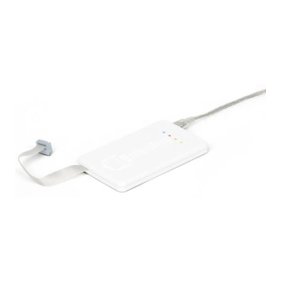
Key features What you see Flat cable USB MINIB connector DATA transfer indication LED ACTIVE indication LED LINK indication LED POWER indication LED Page 5... -
Page 7: Driver Installation
1. Driver installation mikroProg™ requires drivers in order to work. Drivers are Product DVD located on the that you received with the mikroProg™ package: PRODUCT DVD DVD://download/eng/software/ www.mikroe.com www.libstock.com development-tools/avr/avr- prog2/avrprog2_drivers_v200. Copyright ©2012 Mikroelektronika. All rights reserved. MikroElektronika, MikroElektronika logo and other MikroElektronika trademarks are the property of MikroElektronika. -
Page 8: Step 1 - Start Installation
step 1 – Start installation step 2 – Accept EULA In welcome screen click the Next> button Select I accept this EULA option Click the Next> button Page 7... -
Page 9: Step 3 - Installing The Drivers
step 3 – Installing the drivers step 4 – Finish installation Click the Finish button to end installation process Page 8... -
Page 10: Connecting To A Pc
POWER LED should turn ON, indicating the presence of power supply. Amber-colored LINK LED will turn ON when link between mikroProg ™ for AVR ® PC is established. Link can be established only when correct drivers are installed on your PC. -
Page 11: Avrflash Software
3. AVRFlash software mikroProg ™ for AVR ® programmer requires special programming software called AVRFlash. This software is used for programming AVR® microcontrollers from Atmel®. It features intuitive interface and SingleClick ™ programming technology. Software installation comes on a Product... - Page 12 Software installation wizard Start Installation Accept EULA and continue Click Next > button Choose destination folder Installation in progress Finish installation Page 11...
-
Page 13: Connecting With A Target Device
Figure 4-1: IDC10 JTAG connector For connection with a target device mikroProg ™ uses IDC10 connector, as shown on Figure 4-1. In order to make proper connection with the target board it is necessary to pay attention to IDC10 connector pinout. Every pin has a diferent purpose and for easy orientation IDC10 connector is marked with a little knob and incision between pins number 9 and 7, Figure 5-1. -
Page 14: Connector Pinout
5. Connector Pinout MOSI - Master output slave input - Not connected - Reset pin - Clock MISO - Master input slave output - Power supply - Not connected - Not connected - Not connected - Ground Figure 5-1: Female connector pinout Page 13... -
Page 15: Connection Schematic Example
6. Connection schematic example Following example demonstrate connections with one of the most popular supported microcontroller. MCU use MISO, MOSI, SCK and RST lines for programming. In order for microcontroller to work properly, decoupling capacitors must be connected as close as possible to microcontroller’s VCC pins. -
Page 16: 40-Pin Atmega16 Schematic
MOSI MISO PB5 (MOSI) PB6 (MISO) PB7 (SCK) AREF AVCC XTAL2 100nF XTAL1 8MHz 22pF 22pF 40 pin 100nF 100nF Figure 6-1: Connection schematic for 40-pin ATmega16 MCU via 2x5 male header Page 15... - Page 17 Notes: Page 16...
- Page 18 Notes: Page 17...
- Page 19 Notes: Page 18...
- Page 20 Risk Activities. TRADEMARKS The MikroElektronika name and logo, the MikroElektronika logo, mikroC™, mikroBasic™, mikroPascal™, mikroProg™, EasyAVR™, mikromedia™ and Ready™ are trademarks of MikroElektronika. All other trademarks mentioned herein are property of their respective companies. All other product and corporate names appearing in this manual may or may not be registered trademarks or copyrights of their respective companies, and are only used for identiication or explanation and to the owners’...
- Page 21 If you are experiencing some problems with any of our products or just need additional information, please place your ticket at www.mikroe.com/esupport If you have any questions, comments or business proposals, mikroProg for AVR Manual ver. 1.00 oice@mikroe.com do not hesitate to contact us at...
Need help?
Do you have a question about the mikroProg and is the answer not in the manual?
Questions and answers