Table of Contents
Advertisement
Advertisement
Table of Contents

Summary of Contents for Walfront Mach3
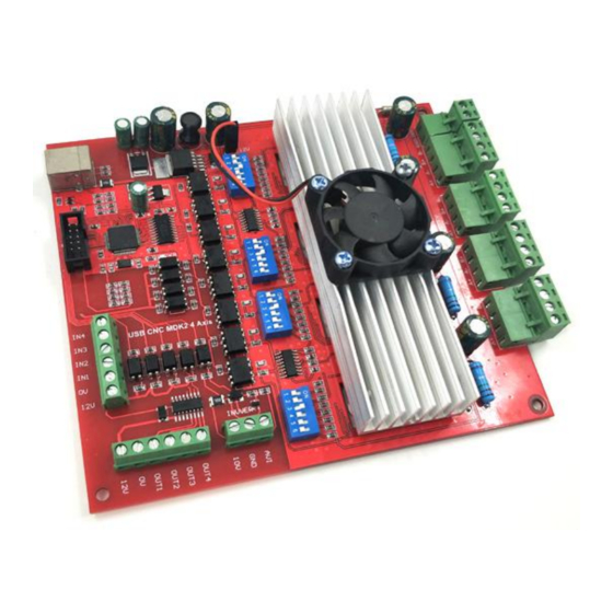
- Page 1 Mach3 USB Motion Card (JDSW43R) Installation Manual...
-
Page 2: Mach3 Usb Motion Card (Jdsw43A) Installation Manual
Mach3 In your test product, make sure the machine's power switch on hand, you can quickly turn off the power. Recommends that users install the emergency stop button and make sure the button is functioning properly. -
Page 3: Table Of Contents
1.3.2 Installing the motion card plug-in..................2.config for mach3: ..........................2.1 Mach3 X、 Y、 Z、 A Axis config as shown below: Config => Ports and Pins): ..2.2 Motor tuning setup as shown below: (Config => Motor Tuning) ........ -
Page 4: Contents
4. Support for connecting electronic handwheel; 5. Have 0-10V signal output , you can use mach3 software to control the spindle motor speed. 6. 4 general-purpose isolated relay drive output interface, can drive four relays for controlling the spindle starts, forward rotating and reverse rotating, pumps or other device;... -
Page 5: Basic Connection Diagram (An Overview)
Basic connection diagram (an Overview):... -
Page 6: Mechanical Dimensions Diagram
Mechanical dimensions diagram:... -
Page 7: Prepare
1.1.Installation the Mach3: 1.Prepare: Open the CD, find mach3 software,run the installation file: Follow the prompts to install, until the last step. The last step requires Note: For 64-bit computer, it is best not to select”LoadMach3 Driver “this one, because it will cause the system to prompt installation errors. -
Page 8: Software License Application
1.2.Software license application: Copy license files “Mach1Lic.dat” from “mach3 software folder”,to C:\Mach3 Cover the original file,Reset Computer ( must reset the computr,please don't open the software dircetly! ) Way 1.3. Installation the software of the USB motion card: above the license for DIY or study purposes only, not for commercial use. -
Page 9: Installing The Motion Card Plug-In
1.3.2 Installing the motion card plug-in. Unzip the usb move.zip, copy or drag RnRMotion.dll into your Mach3\PlugIns folder. 1.3.3 Start the Mach3 software, a dialogue of “Motion Control Hardware PlugIn sensed!” is shown. Please select the“ BSMotion-V2.0”, you can also check”Don't ask me... -
Page 10: Config For Mach3
2.1 Mach3 X、 Y、 Z、 A Axis config as shown below: Config => Ports 2.config for mach3: and Pins): Suggest to put ticks”√ ”, to set low signal levels actived Pick tick “√” After setting, click "Apply" to save the setting results... -
Page 11: Motor Tuning Setup As Shown Below: (Config => Motor Tuning)
3 Velocity Acceleration 2.3 The Mach3 Menu => Config => Homing/Limits dialog: Mach3 steps per unit: Mach3 steps per unit = Mach3 steps per rev x Motor revs per unit Axis direction, depends on the “Reversed” Axis direction: √ Depends on ”... -
Page 12: Setup The Output Signals
2.5 Setup the Output signals: There are 4 general-purpose (open-drain) output channels, The channels number is from O1 to mach3 setup as shown below... -
Page 13: Spindle Speed Control (0-10V) Setup
Don’t forget click “apply” Pin number 1-4 Enter “3” √ Pick ticks” ” Remove √ ” ” Remove √ ” ” M3 code control output 1 output, M4 code control output port 2 output,M5 shut down output 1 and output2. M7 code control output 3 output, M8 code control output port 4 output,M9 shut down output 1 2.6 Spindle speed control (0-10V) Setup: and output2. - Page 14 Completion of the setting, there are two ways to control the output value of 0 ~ 10V. 1. Using the S command. Such as S20000 (the speed to 20000RPM) 2. Using the Mach3 interface control (input Spindle Speed, and adjust Percentage SRO's). Figure:...
-
Page 15: Mach3 Mpg Setup
3.config for drivers: 3.1 Current settings: Torque Settings Current 2.25A 1.5A 0.6A 3.2 Subdivision Subdivision Sub. 3.3 Decay Decay Decay 100% 4.Connection diagrams 4.1 For sensors:... - Page 17 4.2 For Outputs:...
- Page 18 4.2 For Inverter:...
- Page 19 4.2 For Power: DC power must be used,and the Switch DC Power can be 360w/24v. Other cnc parts we have: 1、Belt linear module:...
- Page 25 Ball Screw Actuator linear module:...
- Page 27 Stepper motors and drivers:...
- Page 34 CNC controllers:...
Need help?
Do you have a question about the Mach3 and is the answer not in the manual?
Questions and answers