
Subscribe to Our Youtube Channel
Related Manuals for Paso PA8500-VES

Summary of Contents for Paso PA8500-VES
- Page 1 PA8500-VES Voice Evacuation Systems Cert. EN 54-16: 2008 n° 0068-CPR-082/2013 CR8506-V VES Controller RT8506-V VES Router Instructions for use • Version 1.3...
-
Page 3: Table Of Contents
USING THE SYSTEM....................................33 8.1.. INITIALISING.THE.SYSTEM................................34. 8.2. <MUSIC>.MENU....................................35 8.3. <AUDIO.SETTING>.MENU................................37 8.4. <INSPECTION>.MENU..................................40 8.5. <OPERATOR>.MENU..................................48 8.6. <CONFIGURATION>.MENU................................52 8.7. MANUAL.EMERGENCY.–.<EMERGENCY>.MENU........................56 8.8. AUTOMATIC.EMERGENCY.–.Alarm.Condition.activated.from.an.external.peripheral.unit.............58 FAULT WARNING CONDITION..................................59 9.1. SYSTEM.OPERATION.AND.SIGNALLING.IN.GENERIC.CONDITIONS..................59 9.2. SYSTEM.OPERATION.AND.SIGNALLING.IN.THE.EVENT.OF.A.SPEAkER.LINE.FAILURE............59 TECHNICAL SPECIFICATIONS....................................60 System Manual | 2014 PA8500-VES System... -
Page 4: Introduction
Each CR8506-V controller has provisions for managing 6 control lines.to.which.the.following.units.can.be.connected.directly: •..Digital.power.amplifiers.equipped.with.diagnostics.cards.(PMD range),.up.to.a.maximum.of.16.per.line; •..RT8506-V.router.(1.for.each.line),.capable.of.managing.6.zones.with.a.double.100-V.output.line.(A.and.B); •..Compact.integrated.6-zone.systems.(PA8506-V,.maximum.1.for.each.line); •. Maximum.number.of.zones.in.the.whole.system:.216. It is possible to connect up to a maximum of 6 CR8506-V controllers with one another.controllers with one another. PA8500-VES System System Manual | 2014... - Page 5 CR8506-V | RT8506-V CR8506-V controllers and digital amplifiers of the PMD CR8506-V controller and RT8506-V PA8500-VES | System featuring a mixed configuration System Manual | 2014 PA8500-VES System...
-
Page 6: General Description
R3.. Sockets.for.connections.between.CR8506-V.controllers.(up.to.6.units). R4.. Input.for.connecting.broadcast.paging.units.(PMB106-G, PMG112-G). R5.. Balanced.input.for.a.microphone.or.outside.source./.Terminal.block.for.connecting.a.precedence.contact. R6.. Input.for.external.microphone. R7.. Input.for.connecting.an.external.source.of.music. R8.. 7.monitored.digital.inputs.for.control.via.external.peripheral.units. R9.. 6.output.lines.for.connection.to.amplifiers.of.the.PMD.range.and/or.PA8506-V.compact.systems.and/or.RT8506-V.routers. R10.. Socket.for.connecting.a.Local.Area.Network.with.TCP/IP.protocol.for.an.Ethernet.10/100.network. R11.. 3.relay.outputs.for.signalling.towards.external.peripheral.units.. R12.. Terminals.for.24.VDC.external.power.supply. R13.. Frame.earthing.connection. R14.. Plug.for.230.VAC.mains.power.supply,.with.built-in.fuse. See details of the control panel on page 20. PA8500-VES System System Manual | 2014... -
Page 7: Rt8506-V.router
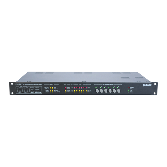
R15.. Terminal.block.for.connection.to.amplifier.outputs. R16.. Loudspeaker.output.terminal.blocks R17.. Programmable.inputs/outputs. R18.. Voice.amplifier.output..-.Music/standby.amplifier.output. R19.. Input/output.for.connection.to.a.CR8506-V.controller. 2.2.1 Main features of the router •. 6.two-line.(A.and.B).loudspeaker.zone.outputs. •. 100-V.double.input.for.1.or.2.voice.amplifiers.(IN.1:.zones.1.to.3,.IN.2:.zones.4.to.6). •. 100-V.input.for.music/standby.amplifier. •. Music.can.be.activated/de-activated.separately.for.each.zone.by.means.of.the.front-panel.push-buttons.provided.for.this.purpose. •. RJ45.sockets.for.connection.to.the.CR8506-V.controller. •. 7.programmable.and.controlled.input.contacts. •. 6.open-collector.outputs. •. 2.relay.outputs. •.. Can.be.mounted.in.a.standard.19”.rack.(height:.1.unit).. System Manual | 2014 PA8500-VES System... -
Page 8: Warnings
For.correct.and.effective.use.of.the.equipment,.it.is.important.to.be.aware.of.all.its.characteristics.by.reading.carefully.these.instructions.and. especially.the.safety.notes..It.is.necessary.to.ensure.adequate.ventilation.while.the.equipment.is.in.use,.and.to.leave.the.side.ventilation.slit.for. the.cooling.fans.unobstructed..Do.not.position.the.equipment.inside.a.cabinet.without.ventilation.and.keep.it.away.from.sources.of.heat..The. equipment.can.be.mounted.in.PASO.standard.19”.racks.. Important information for correct disposal of the product in accordance with EC Directive 2002/96/EC This.product.must.not.be.disposed.of.as.urban.waste.at.the.end.of.its.working.life..It.must.be.taken.to.a.special.waste.collection.centre. licensed.by.the.local.authorities.or.to.a.dealer.providing.this.service..Separate.disposal.of.electric.and/or.electronic.equipment.(WEEE). will.avoid.possible.negative.consequences.for.the.environment.and.for.health.resulting.from.inappropriate.disposal,.and.will.enable.the. constituent.materials.to.be.recovered,.with.significant.savings.in.energy.and.resources..As.a.reminder.of.the.need.to.dispose.of.this. equipment.separately,.the.product.is.marked.with.a.crossed-out.wheeled.dustbin. This product is in keeping with the relevant European Community Directives. PA8500-VES System System Manual | 2014... -
Page 9: Connections
CR8506-V | RT8506-V CONNECTIONS System Manual | 2014 PA8500-VES System... -
Page 10: A) Connection Among Controllers
CR8506-V | RT8506-V CONNECTION AMONG CONTROLLERS Use.Cat.5e.SF/UTP.cables.in.the.‘CR8506-V.LINk’.sockets.(R3).to.connect.the.controllers.of.the.system.(max.6).with.one.another. CONNECTING THE OUTPUT LINES Use.the.‘SLAVE.LINk.OUTPUTS’.sockets.(R9).to.connect.the.following.to.the.controller: B1).RT8506-V.router. B2).PA8506-V compact.emergency.system. B3).Amplifiers.of.the.PMD.range. B1) RT8506-V router Use.Cat.5e.SF/UTP.cables.to.connect.the.‘SLAVE.LINk.OUTPUTS’.sockets.(R9).to.the.‘IN/OUT.SLAVE.LINk’.sockets.on.the.router.. PA8500-VES System System Manual | 2014... - Page 11 CR8506-V | RT8506-V B2) PA8506-V compact emergency system Use.a.Cat.5e.SF/UTP.cable.to.connect.one.of.the.‘SLAVE.LINk.OUTPUTS’.sockets.(R9).to.the.‘REMOTE.LINk’.socket.on.the.PA8506-V. compact.system.. B3) Amplifiers of the PMD range Use.a.Cat.5e.SF/UTP.cable.to.connect.one.of.the.‘SLAVE.LINk.OUTPUTS’.sockets.(R9).to.the.‘IN/OUT’.socket.on.the.amplifier.(PMD125-V,. PMD250-V.or.PMD500-V). System Manual | 2014 PA8500-VES System...
-
Page 12: C) Connecting The Emergency Stations
MUSIC.and.AUDIO.SETTING.menus. A -.Source.of.music.with.unbalanced.output.at.the.level.of.the.line.connected.to.the.AUX.IN.input. To.receive,.select.the.“AUX”.BGM.source.from.the.MUSIC.menu. B -.Receiver.of.the.radio.microphone.kit.with.output.balanced.at.the.level.of.the.microphone.connected.to.the.IN.1.input. To.receive,.select.the.“INPUT.1”.BGM.source.from.the.MUSIC.menu. Set.the.following,.via.the.INPUT.1.panel:. >.MODE:.OFF >.PH:.OFF >.The.Chime,.Priority.and.Zone.list.parameters.have.no.effect. C -.Mixer.with.output.balanced.at.the.level.of.the.Line.connected.to.the.IN.2.LINE.input. To.receive,.select.the.“INPUT.2”.BGM.source.from.the.MUSIC.menu. Set.the.following,.via.the.INPUT.2.panel:. >.MODE:.OFF >.PH:.OFF >.The.Chime,.Priority.and.Zone.List.parameters.have.no.effect. Caution! Do not connect any other equipment to the MIC socket of the IN.2 input. PA8500-VES System System Manual | 2014... - Page 13 >VOL.:.as.desired.(volume.of.the.whole.line. .for.all.the.bases) Set.the.CHIME.panel:. >.UNIT:.ON Sizing:.For.each.CR8506-V.unit,.up.to.a.maximum.of.16.stations.of.the.PAGING.UNITS.range.can.be.connected..Use.the.Cat..5.SF/UTP.connecting. cable,.with.its.shielding.plait..The.following.limits.must.be.observed.for.the.connections: N..1.station.connected.to.a.line.800.metres.long. N..8.stations.distributed.along.2.lines,.each.200.metres.long.(4.stations.per.line). For.systems.calling.for.greater.distances.or.a.higher.number.of.stations.to.be.connected,.it.is.advisable.to.power.the.stations.by.means.of.the.additional. power.supply.unit.connected.to.the.local.socket.of.the.base..The.maximum.length.of.the.connecting.line,.adding.up.the.lines.connected.to.the.two.RJ45. sockets,.is.1.km..For.further.details.concerning.the.type.of.power.supply,.the.configuration.of.the.cable,.programming.of.the.selection.keys.and.setting. of.the.priorities.and.addresses,.refer.to.the.Instruction.Manual.of.the.stations.of.the.PMB.range. The.following.PAGING.UNITS.can.be.connected.to.the.CR8506-V: •. PMB106-G:.6-zone.paging.unit. •. PMB112-G:.12-zone.paging.unit. N.B.: The connections between the CR8506-V and PAGING UNITS must be made solely with CAT. 5e SF/UTP. System Manual | 2014 PA8500-VES System...
-
Page 14: E). Rj45.Input.contacts."Control.inputs
RJ45 INPUT CONTACTS (CONTROL INPUTS) There.are.7.contacts.on.the.CONTROL.INPUTS.(R8).socket..An.example.of.a.connection.is.shown.in.the.figure. N.B.: In the example, contacts 1 to 6 are controlled while contact 7 is not. CONNECTING AN ExTERNAL POWER SUPPLY A.connection.for.a.24.VDC.outside.power.supply.is.available.on.the. terminals.provided.(R12).. CONNECTION TO A PC It.is.possible.to.connect.a.PC.to.the.front-panel.“TO.PC”.socket.(C12).for.downloading.the.configuration.files.from.the.controller.using.the.dedicated. software.(for.details,.see.Section.6.–.Configuration of the system,.page.22). PA8500-VES System System Manual | 2014... -
Page 15: Operating Conditions And Terminology
“Manual Emergency” (LED of the EMERGENCY button ON/flashing) This.procedure.is.performed.by.an.authorised.operator.using.the.manual.controls,.to.activate.VES.sources.or.to.reset.the.Alarms.(Manual.Alarm. Reset)..The.operations.carried.out.in.the.Manual.Emergency.mode.have.a.higher.priority.than.those.activated.by.an.Automatic.Emergency.. A.CR8506-V.unit.or.an.emergency.unit.on.which.the.EMERGENCY.LED.is.illuminated.is.enabled.for.use.for.activating.VES.sources.or.for. resetting.the.alarms..A.CR8506-V.unit.or.an.emergency.unit.on.which.the.EMERGENCY.LED.is.flashing.indicates.that.a.Manual.Emergency. has.been.activated.from.a.remote.station. 5.1.2 Glossary Following.is.a.list.of.definitions.of.terms.used.in.this.manual,.completed.by.indications.of.a.general.nature. “BGM Source”:. One.of.the.following.audio.sources.using.the.“Music”.amplification.channel.(BackGround.Music): -. Audio.source.connected.to.the.AUX.input. -. Flash.memory.device.containing.*.mp3.files.plugged.into.to.the.front-panel.USB.EXT.socket. -. Audio.source.connected.to.the.IN.1.input.(Microphone.input),.set.in.the.IN.OFF.mode. -. Audio.source.connected.to.the.IN.2.input.(Microphone.or.Line.input).set.in.the.IN.OFF.mode. During.a.“Voice.Alarm.Condition”,.the.BGM.sources.are.not.operational. “PA Source”:. One.of.the.following.audio.sources.using.the.”Voice”.amplification.channel.for.Public.Address.announcements: -. Source.of.sound.connected.to.the.IN.1.input.(Microphone.input),.set.in.the.ON.or.PRECEDENCE.MODES. -. Source.of.sound.to.the.IN.2.input.(Microphone.or.Line.input),.set.in.the.ON,.VOX.or.PRECEDENCE.MODES. -. EMERGENCY.UNIT.in.the.broadcasting.mode,.PAGING.UNITS. During.a.“Voice.Alarm.Condition”.the.PA.sources.are.not.operational. System Manual | 2014 PA8500-VES System... - Page 16 VOX functions “Quiescent 1.to.7 condition” PAGING.UNITS..Microphone.stations See.the.manual.of.PMB106-G.&.PMB112-G BGM. Music.source Fixed.setting Source The active sources in the “Voice Alarm” condition always have priority over those active in “Quiescent” condition, regardless of the priority level set. PA8500-VES System System Manual | 2014...
-
Page 17: Equipment.and.functional.specifications
Rear panel R1.. POWER switch ON/OFF.switch.of.the.CR8506-V.system..In.the.O.(OFF).position,.the.system.is.switched.off.and.in.the.I.(ON).position.the.system.is.switched. on..The.switch.affects.only.the.main.230.VAC.power.supply.(see.the.“Power.Supply.and.Earthing”.and.“Safety.Notes”.sections.for.details. about.safety). R2.. EMERGENCY UNITS. Input.for.connecting.remote.emergency.microphone.stations..Use.only.the.PASO.PMB132-V.and/or.PMB132/12-V.microphone.stations.. RJ45.socket.for.connection.with.Cat..5e.SF/UTP.cable.with.a.shielding.braid.and.shielded.STP.connector.(for.details.of.the.connection,. consult.the.manual.of.the.PASO.11/716.stations)..The.EMERGENCY.UNITS.must.be.connected.to.one.another.in.daisy-chain.fashion:. each.of.the.two.connecting.lines.A.and.B.can.reach.a.total.length.of.up.to.1.km. R3.. CR8506-V LINK Sockets for connections among CR8506-V controllers (up to 6).. Connectors.for.connections.among.several.controllers..If.both.LINk.A.and.LINk.B.are.used,.a.redundant.connection.is.achieved.that.keeps. the.system.in.working.order.even.if.one.of.the.two.links.fails..If.more.than.one.controller.is.installed.on.the.same.rack,.it.is.possible.to.use. a.single.LINk.(A.or.B)..if.this.is.done,.it.is.necessary.to.de-activate.the.remote.link.test.not.being.used: . o.Path:.HOME./.CONFIGURATION./. set>.BACkGROUND.TEST ./. 2-Voice.Alarms./.6-Remote.Link.>.Link.Test System Manual | 2014 PA8500-VES System... - Page 18 The batteries and the battery-charger must be installed on the same rack on which the CR8506-V controller is mounted. R13.. Frame connection The.frame.connection.may.be.used.to.connect.other.equipment.only.for.the.purpose.of.shielding.the.low.signals..This.terminal.may.not. be.used.to.connect.the.frame.to.earth.for.safety.purposes..(Consult.the.“Power.supply.and.earthing”.and.“Safety.Notes”.sections.for. details.about.safety). R14.. Plug for 230 VAC mains power with built-in fuse Plug.for.connecting.the.equipment.to.the.230.VAC/50-60Hz.mains.power.using.the.power.cable.supplied.with.it..If.it.is.necessary.to. replace.the.mains.fuse,.this.must.be.done.with.one.of.the.same.type,.i.e..500.mA.fuse,.of.the.miniature.20.mm.cylindrical.type..(consult. the.“Power.supply.and.earthing”.and.“Safety.Notes”.sections.on.page.8.for.details.about.safety). PA8500-VES System System Manual | 2014...
- Page 19 The.yellow.LINE A/B LEDs.indicate.the.following: Flashing Zone.failure:.impedance.measured.on.the.zone.is.out.of.specifications. Steady ON. This.indicates.the.zones.in.which.broadcasting.of.emergency.messages.is.not.envisaged.(DISABLE.function). F7.. PROGRAM INSERTION The.LEDs.indicate.the.following: The.zone.in.which.a.broadcast.call.(NOT.an.emergency.call).is.being.sent.out. Flashing. Steady ON. Background.music.is.activated.for.this.zone.(this.function.is.only.possible.if.there.is.also.an.amplifier.MUS.-SPARE). The.push-buttons.allow.background.music.to.be.activated.in.the.corresponding.zones.(this.function.is.only.possible.if.there.is.also.a.. MUS.-SPARE.amplifier). F8.. Status LEDs Power.supply/call.status.LEDs: •. EMERG.. This.indicates.that.the.system.is.in.a.state.of.emergency. •. CALL. This.indicates.that.a.broadcast.call.is.being.sent.out. •. ON. This.indicates.the.presence.of.the.230.VAC.power.supply. •. BATT.. This.indicates.the.presence.of.the.24.VDC.external.power.supply. System Manual | 2014 PA8500-VES System...
- Page 20 Power.outputs.for.lines.to.speaker.units..Use.only.speaker.units.with.100-V.constant-voltage.line.repeating.coils..Six.output.zones.are. available.and.each.zone.is.split.up.into.two.lines,.A.and.B,.to.create.a.loudspeaker.network.featuring.double.redundant.lines..In.the.event. of.a.short-circuit.on.one.line,.the.RT8506-V.will.de-activate.the.output.for.the.failed.line.and.will.continue.to.power.the.other.line.of.the. same.zone,.activating.a.Failure.signal..12.pairs.of.screw-down.terminals.for.wires.having.cross-sections.of.up.to.2.5.mm .are.available. for.connecting.the.0V-100V.lines. R17.. CONTROL sockets •. 7.monitored.digital.inputs.for.control.via.external.peripheral.units..These.enable.activation.of.programmable.events,.in.Voice.Emergency. conditions,.requiring.pre-recorded.emergency.messages.to.be.sent.out.automatically..Activation.is.possible.via.Normally.Open.or.Normally. Closed.contacts,.relaying.the.+24.VDC.power.supplied.via.the.CONTROL.socket..It.is.possible.to.enable.diagnostics.for.the.connecting. line.by.installing.two.10-kOhm.balancing.resistors.in.the.proximity.of.the.contact.for.activating.the.remote.peripheral.unit..This.connection. calls.for.a.RJ45.socket.with.Cat..5e.SF/UTP.cable. • 6.open-collector.outputs.for.driving.generic.external.or.peripheral.relays..The.PA8500-VES.system.enables.the.logical.outputs.to.be. programmed.to.link.activation.of.the.output.with.system.status.events.or.for.override.functions.in.emergency.conditions.or.for.signalling. failures.relating.to.the.current.emergency.and.to.the.disablement..These.outputs.can.be.programmed.as.Normally.Open.or.Normally. Closed.and.they.have.internal.24.VDC.voltage.with.automatically.resetting.protection.devices..This.connection.calls.for.a.RJ45.socket. with.Cat..5e.SF/UTP.cable. R18.. SPEECH and MUSIC/SPARE microphone sockets •. SPEECH.. Connection.to.the.voice.amplifier(s). •. MUSIC/SPARE. Connection.to.the.music/spare.amplifier.. R19.. SLAVE LINK IN/OUT sockets Input/output.for.connection.to.the.corresponding.sockets.on.the.CR8506-V.controller.(RJ45.socket.with.Cat..5e.SF/UTP.cable). 5.2.3 Controller control panel C1..
- Page 21 This.LED.refers.to.the.24.VDC.auxiliary.power.supply..The.BATT..LED.lights.up.to.indicate.that.the.24.VDC.power.supply.is.connected. to.the.system. •..ON LED (green) This.LED.signals.that.the.CR8506-V.system.is.switched.on.and.operational. The.ON.LED.continues.to.be.illuminated.when: -. 230.VAC.power.supply.present.and.POWER.switch.in.the.ON.position. The.ON.LED.will.flash.continuously.when: -. there.is.no.230.VAC.power.supply.but.the.24.VDC.power.supply.is.available. The.ON.LED.will.be.Off.in.the.following.cases: -. no.230.VAC.and.no.24VDC.power.supply,.or -. 230.VAC.power.supply.in.order,.no.24.VDC.power.supply.and.POWER.switch.in.the.OFF.position.. C10.. +/- knob This.is.a.rotary.control.with.no.end-of-travel..It.is.a.multi-purpose.control.that.depends.on.the.specific.menu.that.is.operational..It.is.used. to.move.the.cursor.to.select.and.adjust.values..In.an.idle.condition,.in.the.Music.menu.it.is.used.to.control.directly.the.master.output. volume.of.the.BGM. C11.. “ExT.” USB socket Powered.type.A.USB.socket.for.connecting.external.flash.memories.. C12.. “TO PC” USB socket Type.B.USB.socket.for.connecting.the.management.PC.to.be.used.with.the.dedicated.system.software. System Manual | 2014 PA8500-VES System...
-
Page 22: Configuration Of The System
*. It is possible at any time to compile a new project by selecting File > New Project. Of course all the previously entered data will be lost since the programme will start again from an empty project. PA8500-VES System System Manual | 2014... -
Page 23: Inserting.the.controllers
Now. configure. the. single. lines. for. each. controller,. starting. from. the. Master.and.setting.the.parameters.for.line.1. Press.LINE 1 > Configure: A.window.will.open.in.which.you.can.select. the.equipment.that.is.connected.to.this.line.(none,.RT8506-V.router,. PMD.amplifiers.or.a.PA8506-V.compact.system). Select.the.required.option.and.click.on.Continue >. Each.option.leads.to.a.specific.dedicated.window,.except.for.“NONE”,. which.returns.the.line.to.an.unused.condition.. • RT8506-V - router If.you.select.this.item,.the.Line 1 configuration.window.will.open,.in.which.you.can.select.the.features.of.the.zones.and.the.input.and.output. contacts.of.the.router..You.can.also.indicate.the.presence.of.amplifiers.connected.to.it..Once.you.have.set.the.parameters,.press.End.(or.Cancel. to.exit.without.saving.the.changes.made).. You.can.find.a.brief.summary.of.the.settings.made.by.clicking.on.LINE 1 > Report.. System Manual | 2014 PA8500-VES System... - Page 24 All the amplifiers connected to a line must necessarily have progressive addresses, from number 1 onwards (max 16 for each line). To set the address of each single amplifier, consult the “Settings” section in the instruction booklet of the PMD range (PASO code number 11/733).
- Page 25 Press.CTR OUTPUT > Configure..The.Controller.0.output.configuration. window.will.open,.in.which.–.as.already.seen.for.the.inputs.–.you.can. associate.the.required.parameters.with.each.of.the.3.contacts. Press.End.to.save.the.configuration,.or.press.Canc..to.cancel.it.and. return.to.the.main.window. • EMERGENCY UNITS Press. EMERGENCY UNITS > Configure.. The. window. for. configuring. the. emergency. stations. that. can. be. connected. will. open. To.set.a.specific.configuration.for.the.keys.associated.with.each. emergency.station,.press.the.relevant.Key Conf.:.It.is.possible. to.call.up.a.configuration.that.has.already.been.defined.(see. “Configuring.groups.of.zones”).or.to.make.changes.manually.to. the.default.configuration.prompted.in.the.‘Unit.key.list’.box. Press.End.to.save.the.configuration,.or.press.Canc..to. cancel.it.and.return.to.the.main.window. System Manual | 2014 PA8500-VES System...
- Page 26 From.the.list.on.the.left-hand.side,.select.the.zone.or.the.configuration. you.wish.to.associate.with.it,.then.click.on.the.central.arrows..The.new. combination.selected.by.you.will.appear.immediately.on.the.list.on.the. right-hand.side. Press.End.to.save.the.configuration,.or.press.Canc..to. cancel.it.and.return.to.the.main.window. • Configuring groups of zones From.the.menu,.select.View > Key configuration.to.open.a.complete.schedule.of.the.zones.referred.to.the.controllers.installed.in.the.system.. Against.a.white.background,.the.window.will.show.the.number.of.units.and.zones.that.have.been.set..For.each.controller,.the.active.zones.are. shown.in.red..The.status.of.each.zone.can.be.altered.simply.by.clicking.on.the.number,.which.will.turn.green... After.setting.the.zones.you.require,.click.on.Save.to.save.the.configuration..To.create.the.next.configuration.file,.select.the.name.in.the.drop-down. menu.as.before..In.this.window,.you.can.set.up.to.64.configuration.files,.which.you.can.call.up.in.the.configuration.windows.of.the.stations.(see. previous.sections). PA8500-VES System System Manual | 2014...
- Page 27 N.B.. The files to be used must necessarily be recorded in and /or converted into the *.WAV 48 ksample 16bit audio format. Once.you.have.loaded.the.file,.you.can.indicate. whether.it.is.a.message.to.be.sent.in.warning. situations.(Alert).or.in.evacuation.situations. (Evac). It.is.also.possible.to.add.a.brief.description.of. each.message.entered.(max.25.digits). In.addition.to.voice.messages,.a.warning.tone. (Chime).can.also.be.entered,.using.the.same. procedure. Press.End.to.save.the.configuration,.or.press. Canc..to.cancel.it.and.return.to.the.main.window. Once.you.have.completed.configuring.CONTROLLER.0,.save.the.project.and.click.on.the.“CONTROLLER.1”.tab.to.proceed.with.its. configuration. System Manual | 2014 PA8500-VES System...
- Page 28 • Connection to a PC via USB It.is.possible.to.connect.the.controller.to.a.PC.so.as.to.upload.and/or.download.configuration.files.and.messages. from/to.the.equipment..The.PC.must.have.a.Windows.Vista®,.Windows.7®.or.higher.operating.system.and.a.USB. 2.0.port...To.make.this.connection,.it.is.necessary.to.proceed.as.follows: 1). First.of.all,.before.making.the.connection.to.the.controller,.install.the.software.on.the.PC; 2). Plug.a.USB/MiniUSB.cable.into.the.front-panel.“TO.PC”.socket.of.the.controller.(C12); 3). Plug.the.other.end.of.the.cable.into.one.of.the.USB.2.0.sockets.on.the.PC; 4). Wait.for.the.operating.system.to.load.the.driver.of.the.device..The.Virtual.Com.Port.icon.(in.the.example,.this.is.COM10).will.appear.in.the. “Devices.and.printers”.section.of.the.control.panel; 5). From.the.menu,.select.Tools > USB connection;.you.will.be.asked.to.indicate..the.communications.port.to.be.used.(in.our.example,.select. COM10); 6). In.the.box,.enter.the.configuration.password.that.is.active.on.the.controller.(3333,.which.is.the.factory.setting).and.press.Ok. The.controller.and.the.PC.are.now.able.to.communicate.with.one.another..The.PA8500-VES Usb connection.page.will.open,.and.from.here.it. will.be.possible.to.proceed.as.follows: A). To.change.the.address.of.the.controller:.enter.the.new.address.(from.0.to.5).and.press.“Change”. B). To.download.the.configuration.files.and/or.messages.from.the.PC.to.the.controller.(this.function.is.only.enabled.if.a.project.has.been.opened. and.saved)..If.this.operation.is.used.to.up-date.the.configuration.of.a.controller,.it.is.advisable.to.repeat.the.same.procedure.also.for.all.the. remaining.controllers.of.the.system,.using.the.“Complete.configuration”.option. PA8500-VES System System Manual | 2014...
- Page 29 SD card must be created for each controller in the system. Each single card will contain the information relating both to the specific controller and to the rest of the system. After.making.sure.that.CONTROLLER.0.is.switched.off,.use.a.screwdriver.to.unscrew.the.small.cover.at.the.centre.of.the.rear.panel.and.remove. Insert.the.SD.into.the.drive.of.the.PC,.then.select.the.CONTROLLER.0.window..From.the.main.menu,.select.Tools > Create SD..The.card.will. be.formatted.and.then.automatically.programmed.with.the.necessary.data. Once.writing.has.been.completed,.remove.the.SD.card.from.the.PC,.then.plug.it.into.its.slot.in.the.rear.panel.of.CONTROLLER.0..Put.the.cover. back.into.place.and.fix.it.with.the.screws.removed.earlier. Repeat.these.operations.for.all.the.other.controllers.(in.the.example,.CONTROLLER.1). System Manual | 2014 PA8500-VES System...
-
Page 30: Menu Structure
After.switching.on.the.system,.the.MUSIC.Management.Window.will.be.shown.directly..To access the HOME page, press the MENU key. From the HOME page it will be possible to select the various different Option Menus for the advanced functions of the system..From the HOME page, press ESC to return to the MUSIC management panel. MENU PA8500-VES System System Manual | 2014... - Page 31 7.1.4 System Level - OPERATOR Menu From.the.HOME.page,.turn.the.knob,.then.press.Ok.to.select.the.item.OPERATOR:.to.access.the.menu.in.question.it.is.it.is.necessary. to.enter.a.password.and.then.press.Ok.again..As.an.alternative.press.ESC.to.return.to.the.MUSIC.menu. From.the.OPERATOR.menu,.use.the.knob.at.the.side.of.the.display.unit.to.browse.through. the.options.listed.and.select.the.one.you.require.using.the.Ok.key..Press.ESC.to.return.to. the.MUSIC.menu.or.MENU.to.return.to.the.HOME.page...For the specific features for each panel for managing the OPERATOR menu, refer to the appropriate schedules in Section 8. USING THE SYSTEM / 8.5 < OPERATOR Menu >. System Manual | 2014 PA8500-VES System...
- Page 32 For the specific features for each panel for managing the CONFIGURATION/ SERVICE menu, refer to the appropriate schedules in Section 8. USING THE SYSTEM / 8.6 < CONFIGURATION menu >. 7.1.6 System Level - SERVICE Menu Access.the.CONFIGURATION.menu.then.use.the.knob.at.the.side.of.the.display.unit.to.scroll.to.the.<SERVICE>.option.and.press. Ok.to.select.it..To.access.the.menu.in.question.it.is.necessary.to.enter.another.password.and.then.press.Ok.again..As.an.alternative. press.ESC.to.return.to.the.MUSIC.menu. The.Functional.Specifications.of.the.panels.for.managing.the. SERVICE.menu.are.the.responsibility.of.the.Service.personnel. and.beyond.the.scope.of.this.User.Manual..They.are.therefore. not.illustrated.here. PA8500-VES System System Manual | 2014...
-
Page 33: Using The System
If. the. system. is. being. used. for. the. first. time,. or. if. the. configuration. has. been.changed,.proceed.according.to.the.indications.shown.in.the.section. 8.1 Initialising the system..If.the.initialise.procedure.is.complete,.see.the. instructions.of.the.following.sections: •. For.normal.use.of.background.music.and.voice.announcements,.users.can. use.just.MUSIC.and.AUDIO.SETTING.menu. •. For. the. management. of. advanced. features. during. fault,. emergency. and. configuration.condition,.see.the.following.menu.INSPECTION,.OPERATOR,. and.EMERGENCY.CONFIGURATION. •. To.reset.the.“beep”,.consult.the.OPERATOR.Section.(point.8.5.3.1,.. page.51). The.functions.associated.with.levels.featuring. restricted.access,.for.which.a.password.may.be.set,. •. To.send.emergency.messages,.consult.the.MANUAL.EMERGENCY. are.highlighted.by.this.symbol. Section.(point.8.7,.page.56). System Manual | 2014 PA8500-VES System... -
Page 34: Initialising.the.system
•.Volume control Adjust.the.output.volume.of.the.VES.sources.suitably.so.as.to.ensure.that.the.messages.are.as.intelligible.as.possible..The.level.set.will.be.used. for.”Voice.Alarm.Conditions”.and.will.be.the.same.for.all.the.zones..To.adjust.the.volume.of.the.Emergency.Microphone.and.of.the.ALERT.and. EVAC.messages,.follow.the.instructions..provided.under.“ALARM.LEVEL”.(point 8.6.4, page 55). o.Path:.HOME./.CONFIGURATION./. set>.ALARM.LEVEL •.Resetting failures Upon.completion.of.the.system.configuration,.the.reports.concerning.failure.that.have.been.stored.and.cleared.should.be.cancelled.(RESOLVED).. A.FAULT.RESET.should.therefore.be.carried.out.as.indicated.under.“FAULTS” (point 8.5.3.1, page 51). o.Path:.HOME./.CONFIGURATION./. report>.FAULT,.access.the.subpanels.for.viewing.failures . •.After initialising the system After.completing.the.system.initialisation.procedure,.LOG.OUT.in.order.to.reinstate.any.access.restrictions.associated.with.passwords.(point 8.5.5, page 51). o.Path:.HOME./.CONFIGURATION./. Exit>.Logout. (press.the.Ok.key). PA8500-VES System System Manual | 2014... -
Page 35: Music>.Menu
N.B.: Adjustment is not possible on those lines to which an RT8506-V router is connected. 8.2.4 Activation and de-activation of music for each output zone •.Press.and.then.release.the.numerical.key.of.the.required.zone.(from 1 to 6). The.status.label.(B).will.switch.between.OFF.(music.disabled).and.ndB.(music.ON.and.associated.output.volume). Note: The.CR8506-V.system.enables.service.announcements.to.be.made.from.a.PA.Source.to.the.required.zones.while.continuing.to.broadcast. music.to.all.the.other.zones.not.affected.by.the.call..When.an.announcement.is.being.made,.the.display.will.show.the.source.that.is.being.used. on.the.voice.channel.(D),.and.the.status.label.of.each.zone.selected.(B).will.indicate.the.word.CALL.. Service.announcements.will.be.broadcast.at.the.volume.set.for.the.input.of.the.PA.Source.(see.AUDIO.SETTINGS.menu).and.if.appropriate.will. also.be.sent.to.the.zones.for.which.music.is.de-activated.(OFF). System Manual | 2014 PA8500-VES System... - Page 36 In.both.cases,.while.the.track.is.being.played.out.the.display.will.show.the. name.of.the.file.and.the.name.of.the.current.folder. It.is.also.possible.to.choose.between.three.different.modes.for.playing. out/repeating.the.tracks,.simply.by.pressing.key.(6): Note: SINGLE. to.play.out.all.the.tracks.of.the.active.folder.once If.an.Automatic.or.Manual.Emergency.is.activated,. RPT.FLD. to.repeat.all.the.tracks.of.the.active.folder.cyclically the.track.being.played.out.will.be.stopped..Once.the. RPT.ALL. to.repeat.all.the.tracks.contained.in.the.flash.memory... Emergency.has.been.cleared,.press.PLAY.to.resume. cyclically. playing. • Requisites for audio files for the USC music source The.files.must.be.in.the.*.mp3.format.(44.100.kS/sec).and.may.be. contained.either.in.the.root.directory.or.in.secondary.directories,.if.any. Any.files.contained.in.second-level.directories,.on.the.other.hand,.will.not. be.read.(see.figure.opposite). Note: If.an.Automatic.or.Manual.Emergency.is.activated,.playing.out.of.the.track. will.STOP..Once.the.Emergency.has.ceased,.to.resume.playing.out.press. PLAY. PA8500-VES System System Manual | 2014...
-
Page 37: Audio.setting>.Menu
Inputs. programmed. to. activate. announcements. by. means. of. precedence.or.VOX.contacts. Reference.values: ON=Chime.active OFF=Chime.not.active •...Adjustment of the volume of the Chime tone: Hold.down.key.1.and.use.the.+/-.knob.to.adjust.the.volume.within.the.range.from.0.to.255;.the.volume.is.common.to.all.four.inputs.and.is.separate. from.the.volume.adjustment.assigned.to.the.sources. • Loading the Chime tone: The Chime audio file is managed by the dedicated software (see page 27). System Manual | 2014 PA8500-VES System... - Page 38 . .>.C. 1 ÷ Z. 64:. To. select. a. pre-established. group. of. zones. (these. configurations. can. be. created. using. the. controller.exe. software).in.which.to.broadcast.the.calls/music. •.3-Hold on: To.set.the.release.time.after.an.input.signal,.when.the.VOX.mode.is.selected... Hold.down.key 3 (Hold.on).then.turn.the.+/-.knob.to.choose.a.time.(between.1.and.99.secs.). •.4-Priority: Priority.assigned.to.an.input.when.it.is.used.as.a.voice.source.for.service.announcements..There.are.7.priority.levels..The.input.can. be.muted.by.another.voice.source.featuring.a.higher.level.of.priority..Hold.down.key.4.(Priority).then.turn.the.+/-.knob.to.choose.the. required.level. •.5-Sensitivity: Adjustment.of.sensitivity..Press.key.5.(Sensitivity).to.choose.the.required.level.(between.0,.6,.12.or.18.dB).. •.6-Phantom: Setting.of.the.Phantom.power.supply.(OFF.=.not.active./.ON.=.active)..To.change.the.setting,.press.key.6 (Phantom),.then.release. The.RESET,.ALERT,.EVAC,.MENU.and.Ok.have.no.functions. Press.ESC.to.return.to.the.AUDIO.SETTINGS.menu. PA8500-VES System System Manual | 2014...
- Page 39 . .>.C. 1 ÷ Z. 64:. To. select. a. pre-established. group. of. zones. (these. configurations. can. be. created. using. the. controller.exe. software).in.which.to.broadcast.the.calls/music. •.3-Hold on: To.set.the.release.time.after.an.input.signal,.when.the.VOX.mode.is.selected... Hold.down.key 3 (Hold.on).then.turn.the.+/-.knob.to.choose.a.time.(between.1.and.99.secs.). •.4-Priority: Priority.assigned.to.an.input.when.it.is.used.as.a.voice.source.for.service.announcements..There.are.7.priority.levels..The.input.can. be.muted.by.another.voice.source.featuring.a.higher.level.of.priority..Hold.down.key.4.(Priority).then.turn.the.+/-.knob.to.choose.the. required.level. •.5-Sensitivity: Adjustment.of.sensitivity..Press.key.5.(Sensitivity).to.choose.the.required.level.(between.0,.6,.12.or.18.dB).. •.6-Phantom: Setting.of.the.Phantom.power.supply.(OFF.=.not.active./.ON.=.active)..To.change.the.setting,.press.key.6 (Phantom),.then.release. The.RESET,.ALERT,.EVAC,.MENU.and.Ok.have.no.functions. Press.ESC.to.return.to.the.AUDIO.SETTINGS.menu. System Manual | 2014 PA8500-VES System...
-
Page 40: Inspection>.Menu
CTR CONFIGURATION panel.(from.the.report> CONFIG option) To.display.the.system.configuration. 8.4.4 CONTROL INPUT STATUS panel.(from.the.status> CONTROL INPUT option) For.viewing.in.real.time.the.status.of.the.input.contacts.of.the.CR8506-V.that.can.activate.an.Automatic.Emergency. 8.4.5 INDICATORS TEST panel.(from.the.test> INDICATORS option) For.checking.the.functionality.of.the.signalling.elements.connected.with.the.emergency.(buzzer.loudspeaker,.display.and.LEDs) < OPERATOR > Passaggio.diretto.al.menu.OPERATOR.(point 8.5, page 48). < CONFIGURATION > Passaggio.diretto.al.menu.CONFIGURATION.(point 8.6, page 52). PA8500-VES System System Manual | 2014... - Page 41 Ground.fault.loudspeaker.lines Primary.and.secondary.power.supplies. At.least.1.fault.detected.. 4-Power.Supply POWER.SUPPLY.FAULTS FAULT Management.memory.display and.on-going. 5-Control.Input Local.input.contacts CONTROL.INPUT.FAULT At.least.1.fault.cleared.. CR8506-V.internal.data. and.no.on-going.faults 6-Communication COMMUNICATION.FAULT communication Tab..8.4.1.1 8.4.1.1 Automatic resetting of the acoustic signal (beep) following clearing of a failure If.the.cause.of.a.failure.is.cleared.before.the.beep.is.reset.manually.(see.OPERATOR.Menu,.point.8.5.3.1,.page.51),.the.CR8506-V.will.reset. the.beep.automatically,.extinguish.the.FAULT.LED.and.indicate.RES.(RESUMED).in.the.label.of.the.part.that.had.FAILED..The.RESOLVED. signal.will.be.stored.until.a.MANUAL.RESET.of.the.failure.signal.is.carried.out.from.the.FAULTS.panel.via.the.OPERATOR.menu. System Manual | 2014 PA8500-VES System...
- Page 42 TOLERANCE panel (point 8.6.2, page 51). 8.4.1.3 VOICE ALARMS FAULT Diagnosing faults of the VES emergency sources From. the. FAULT. panel. (point. 8.4.1),. press. numerical. key. 2. and. access. the.panel.for.viewing.the.diagnostics.of.the.VES.emergency.sources..The. diagnostic.state.of.each.item.monitored.is.reported,.as.shown.in.the.following. table. For.some.items.of.equipment.it.may.be.necessary.to.access.the.sub-panel,. by.pressing.the.corresponding.numbered.key. Press.ESC.to.return.to.the.panel.FAULTS. PA8500-VES System System Manual | 2014...
- Page 43 CAT5.connection.to:. -.PMD. Check.the.connections..If the failure persists, 5-Line.connect. Fault -.RT. contact the Service Centre. -.AMP Communication.error. Press.key.6.to.access.the.dedicated.“LINk. FAULTS”.panel..Check.the.connecting.cables. Intercommunication.with. between.the.CR8506-V.units.for.connection. 6-Remote.Link Fault remote.CR8506-V.units CR8506-V.LINk.. If the failure persists, contact the Service Centre. Tab..8.4.1.3 System Manual | 2014 PA8500-VES System...
- Page 44 Amplifiers.of.the.PMD. range.connected.to.the. Out.20kHz. Make.sure.that.the.amplifier.has.been. Amplifier.n controller.or.AW5624/48. Make.sure.that.there.is.an. connected.to.the.network.and.switched.on. amplifiers.connected.to. output.signal.on.the.line. If the failure persists, contact the Service the.router Centre. Gnd.Fault. Check.the.connections.of.the.loudspeaker. Check.the.insulation.between. lines. If the failure persists, contact the the.loudspeaker.lines.and. Service Centre. earth. Tab..8.4.1.4 PA8500-VES System System Manual | 2014...
- Page 45 Centre. Check.the.24.VDC.power.supply,.the. Secondary.power. Secondary.power.supply.of.the. connecting.cable.and.the.mains.fuse..4-Rtr/PA.24VDC supply.of.the.router/ router.or.PA8506-V.not.detected If the failure persists, contact the Service PA.@24V Centre. .Ctr.display Controller.display. Fault Upset.detected.on.display Contact the Service Centre. .PA.display PA8506-V.display Fault Upset.detected.on.display Contact the Service Centre. Tab..8.4.1.5 System Manual | 2014 PA8500-VES System...
- Page 46 Display Cause Action required Data.communications.between.the.CPU. I2C.bus Fault Internal.communication.failure. Contact the Service Centre. and.the.keys.and.front-panel.LEDs Data.communication.between.CPUs. Fault Internal.communication.failure. Contact the Service Centre. Tab..8.4.1.7 8.4.2 IMP. REAL TIME |.Real-time line impedance Panel.for.checking.the.impedance.values.measured.in.real.time,.and.percentage.variations.from.the.value.stored.during.start-up,.using.the.“Line. impedance.acquisition”.procedure..The.lines.being.used.are.listed..You.can.select.a.numerical.key.to.access.the.corresponding.panel.indicating. the.impedance.measured.in.Ohms.referred.to.the.parallel.of.lines.A.and.B.connected.to.that.line.. If.the.percentage.of.variation.exceeds.the.level.of.tolerance.set.at.the.time.of.configuring.the.system,.a.“LOUDSPk.LINE.FAULT”.due.to.an. excessively.high.or.low.impedance.(Impedance.Hi.or.Impedance.Low).will.be.signalled. Press.ESC.to.return.to.the.INSPECTION.panel. PA8500-VES System System Manual | 2014...
- Page 47 (see table). Low.priority Pre-recorded.Alert.message.(ALERT) Minimum.priority No.event.(NONE) Press.ESC.to.return.to.the.INSPECTION.panel. 8.4.5 INDICATORS TEST Check of the functionality of the visual and audio signal elements Panel.for.checking.speaker.functionality.(BEEP),.display.and.operating.emergency.LED.indicators..All.LEDs.on.the.front.panel.(excluding.‘ON’. LED).and.the.EMERGENCY.key.LED.are.flashing..A.horizontal.bar.running.for.the.whole.width.of.the.display.is.also.activated.and.the.warning. signal.(BEEP).will.sound.for.about.three.seconds..The.functionality.of.the.built-in.speaker,.all.LEDs.and.all.the.display.pixels.are.checked.. Please.contact.Support.in.case.of.failure..Press.ESC.to.return.to.the.INSPECTION.panel. System Manual | 2014 PA8500-VES System...
-
Page 48: Operator>.Menu
BACKGROUND TEST panel.(via.the.set > BACKGROUND TEST option) For.enabling.and.disabling.monitoring.of.parts.affecting.the.ability.of.the.system.to.function.in.emergency.conditions. 8.5.3 FAULTS panel.(via.the.report > FAULTS option) query.concerning.the.status.of.current.and.cleared.failures.as.described.in.the.Section.on.INSPECTION..In.addition,.this.level.enables. MANUAL.RESETTING.OF.FAILURE.SIGNALS. 8.5.4 FIRMWARE VERSION panel.(via.the.Firmware Version option) This.panel.shows.the.version.of.the.firmware.installed.in.the.system. < INSPECTION > For.going.directly.to.the.INSPECTION.menu. < CONFIGURATION > For.going.directly.to.the.CONFIGURATION.menu. 8.5.5 Exit > Logout option To.exit.from.the.service.level.and.return.to.the.basic.level,.reinstating.the.access.password. PA8500-VES System System Manual | 2014... - Page 49 •.. Press.the.corresponding.numerical.key.to.select.required.item.for.opening. the.sub-menu.and.then.to.enable.or.disable.the.diagnostic.test.(on.=.test. enabled./.off =.test.disabled): > 1-Local Emerg. >.1-Microphone. >.2-Emerg..button > 2-Configuration. >.1-SD.card. >.2-Msg.table > 3-Emerg. Unit. >.1-Ctr.unit.<1>. > 4-Messages. >.1-Evac.message >.2-Alert.message > 5-Line connect.. >.1÷6-Line.n.connect.. > 6-Remote Link:. >.1-Remote.link.A >.2-Remote.link.B >.3-Remote.ctr Note:.The.display.will.show.the.programming.that.has.been.set. Press.ESC.to.return.to.the.BACkGROUND.TEST.panel. System Manual | 2014 PA8500-VES System...
- Page 50 Enabling of testing of controlled inputs Panel.for.enabling.and.disabling.the.monitoring.tests.applied.to.the. controlled.inputs. •...Press.the.appropriate.numerical.key.to.enable.or.disable.the.diagnostic. test: >.1-Controller.IN. (on.=.test.enabled./.off =.test.disabled) >.2-Rtr/PA.IN. (on.=.test.enabled./.off =.test.disabled). Note:.The.display.will.show.the.programming.that.has.been.set. Press.ESC.to.return.to.the.BACkGROUND.TEST.panel. 8.5.2.5 COMMUNICATION Setting the test for internal data communication Panel.for.enabling.and.disabling.testing.applied.to.communication.data. between.internal.sections.of.CR8506-V. •...Press.the.appropriate.numerical.key.to.enable.or.disable.the diagnostic.test: >.1-Communication. (on.=.test.enabled./.off =.test.disabled). Note:.The.display.will.show.the.programming.that.has.been.set. Press.ESC.to.return.to.the.BACkGROUND.TEST.panel. PA8500-VES System System Manual | 2014...
- Page 51 >. Firmware z (zones): Main.software.installed.on.the.CPU.for.managing.the.zones.. >. Fpga: Digital.audio-signal.matrix. >. Data conf: Configuration.data.structure. 8.5.5 Exit > Logout Exiting from a System Level Upon.completing.the.various.activities,.before.returning.to.the.Basic.Level.of. the.Music.Menu,.it.is.advisable.to.log.out.of.the.System.Level.of.the.current. menu,.in.order.to.reinstate.the.password.required.for.accessing.the.system. again.in.future,.thus.preventing.unauthorised.personnel.from.accessing.the. advanced.functions.of.the.system. From.the.options.list.of.the.OPERATOR.MENU: •.turn.the.+/-.knob.to.select.the.following.option: Exit> Logout •.press.the.Ok.key The.system.will.return.to.the.Basic.Level,.showing.the.MUSIC.Menu.panel.. The.prompt.requiring.the.access.password.to.be.entered.will.also.be.rein- stated.for.any.other.levels.that.had.been.reached. System Manual | 2014 PA8500-VES System...
-
Page 52: Configuration.menu..turn.the.knob.to.browse.through.the.options.listed
DISABLEMENT panel.(via.the.set > DISABLEMENT option) For.disabling,.in.one.or.more.emergency.zones,.the.activity.envisaged.for.an.“Alarm.Condition”.(Voice.Alarm.Condition)..If.at.least.one.zone.is. set.to.a.“Disablement.Condition”,.the.dedicated.“DIS.”.LED.will.signal.the.existence.of.a.“Disablement.Condition”. 8.6.7 PASSWORD panel.(via.the.Password option) Panel.for.enabling,.disabling.and.customising.the.password.for.accessing.the.system.service.levels. 8.6.8 BEEP OPERATION panel.(via.the.Beep operation option) Panel.for.enabling,.disabling.and.customising.the.system.beep. < SERVICE > Connection.to.the.SERVICE.menu.for.technical.personnel.having.the.necessary.password..It.is.used.to.change.the.operating. parameters.of.the.CR8506-V.system,.up-dating.the.firmware.and.servicing.it. Note: The settings of the Service Menu are not covered in this Manual. PA8500-VES System System Manual | 2014... - Page 53 After. s electing. t he. “ Set>. I MP.. T OLERANCE”. o ption. f rom. t he. C ONFIGURATION. menu,.the.“SET.TOLERANCE”.panel.will.show.the.current.tolerance.settings. for.each.output.zone. •.press.the.numerical.key.corresponding.to.the.line.. •.Hold.the.numerical.key.corresponding.to.the.zone.(1-6).down,..turning.the.+/-.knob.to.choose.the.required.value. >Valori da 10% a 100%: tolerance.above.or.below.the.stored.value. >Test Disabled: Impedance.check.disabled..Testing.for.short.circuits.and. GND.faults.will.in.any.case.be.carried.out. It.is.also.possible.to.disable.the.impedance.test.by.setting.a.tolerance.of. 0%.(Not.Tested). Press.ESC.to.return.to.the.CONFIGURATION.menu. Upon.completion.of.the.procedure,.if.appropriate.carry.out.a.MANUAL. RESET.OF.THE.FAILURE.SIGNALLING.as.described.under.point.8.5.3.1, page 51. System Manual | 2014 PA8500-VES System...
- Page 54 >.1-Link.A.level...>.Press.key.1.then.turn.the.+/-.knob. >.2-Link.B.level...>.Press.key.2.then.turn.the.+/-.knob. > 3-Link speech lev.. Output.levels.of.the.20.kHz.speech.output.signal.sent.towards.the.other.controllers. connected.to.the.system.. >.1-Link.A.level...>.Press.key.1.then.turn.the.+/-.knob. >.2-Link.B.level...>.Press.key.2.then.turn.the.+/-.knob. > 4-Line music lev. Music.channel.test.levels.. >.1-Line.1.level...>.Press.key.1.then.turn.the.+/-.knob. >.2-Line.2.level...>.Press.key.2.then.turn.the.+/-.knob. >.3-Line.3.level...>.Press.key.3.then.turn.the.+/-.knob. >.4-Line.4.level...>.Press.key.4.then.turn.the.+/-.knob. >.5-Line.5.level...>.Press.key.5.then.turn.the.+/-.knob. >.6-Line.6.level...>.Press.key.6.then.turn.the.+/-.knob. > 5-Line speech lev. Voice.channel.test.levels.. >.1-Line.1.level...>.Press.key.1.then.turn.the.+/-.knob. >.2-Line.2.level...>.Press.key.2.then.turn.the.+/-.knob. >.3-Line.3.level...>.Press.key.3.then.turn.the.+/-.knob. >.4-Line.4.level...>.Press.key.4.then.turn.the.+/-.knob. >.5-Line.5.level...>.Press.key.5.then.turn.the.+/-.knob. >.6-Line.6.level...>.Press.key.6.then.turn.the.+/-.knob. N.B.:.The.display.shows.the.status.of.the.factory-set.programming.. Press.ESC.to.return.to.20kHZ.LEVEL.SETTINGS.panel. PA8500-VES System System Manual | 2014...
- Page 55 (CONTROL. INPUTS). are. programmed. and. of. how. the. Operator. proceeds. during. a. Manual. Emergency. procedure.. . The. “disabled”. zone. will. therefore. not. be. affected. by. a. “Voice. Alarm. Condition”.of.the.system.. The.status.label.of.each.zone.will.signal.a.possible.“Disablement.Condition”.set.with.a.priority.higher.than.the.signals.called.for.by.a.“Voice.Alarm. Condition”.and.a.“Fault.Warning.Condition”..During.a.Manual.Emergency.procedure,.it.will.not.be.possible.to.select.the.disabled.zone.for.sending. alarm.messages..For.details.consult.point.8.8. System Manual | 2014 PA8500-VES System...
-
Page 56: Manual.emergency.-.
Activation. of. the. emergency. mode. will. also. be. shown. on. the. routers,. stations.and.any.other.controllers.connected.to.the.controller. -. Send.a.voice.message.(using.the.hand-held.microphone).or.an.alerting. message.(ALERT.key).or.evacuation.message.(EVAC.key).to.all.zones.. The.display.will.show.the.type.of.message.being.broadcast. N.B.: Messages sent using a hand-held microphone have absolute priority over pre-recorded evacuation and alert messages. To.end.live.emergency.messages,.alert.messages.and/or.evacuation.messages,.press.the.EMERGENCY.key.again. PA8500-VES System System Manual | 2014....Menu - Page 57 C) ExITING THE SYSTEM FROM MANUAL MANAGEMENT OF THE EMERGENCY Upon.completion.of.the.Manual.Emergency.management.procedure,.press.the.red.EMERGENCY.key,.which.will.extinguish,.and:. -. If. no. alarms. from. external. peripheral. units. connected. to. the. input. contacts. (Control. Inputs). have. been. activated,. then. the. system. will. automatically.revert.to.the.“Idle”.status,.displaying.the.<MUSIC>.menu..The.ALARM.LED.will.remain.OFF.to.indicate.that.the.VOICE.ALARM. condition.is.not.active. -. If.any.alarms.from.external.peripheral.units.connected.to.the.input.contacts.(Control.Inputs).have.been.activated,.then.the.system.will.revert. to.the.Automatic.Emergency.mode,.displaying.the.INPUT.ALARM.STATUS.menu..Broadcasting.of.the.emergency.messages.will.resume. as.programmed.for.the.inputs.that.have.been.activated,.and.the.ALARM.LED.will.light.up,.if.appropriate,.to.indicate.activation.of.a.VOICE. ALARM. System Manual | 2014 PA8500-VES System...
-
Page 58: Automatic.emergency.-.Alarm.condition.activated.from.an.external.peripheral.unit
-. A. current. “Voice.Alarm. Condition”. due. to. an.Automatic. Emergency. may. be. altered. by. an. authorised. operator. entering. the. system. to. activate. the. manual.controls.for.managing.the.emergency,.in.order.to.RESET.the.messages,.change.the.current.messages.or.send.live.announcements.using.the. microphone.provided.for.this.purpose. For.details.about.management.of.a.Manual.Emergency,.consult.the.MANUAL.EMERGENCY,.point.8.7,.page.56. Exiting from an Automatic Emergency 8.8.3 •.De-activate.the.contact.that.had.activated.the.emergency..or •.Press.the.EMERGENCY.push-button..At.the.same.time,.hold.the.RESET.key.down.for.at.least.2.seconds,.then.release.it. To.inform.the.operator.that.the.alarm.was.activated.via.external.contacts,.the.controller.keeps.the.notice.of.the.emergency.flashing.on.the.display. The.system.will.return.to.a.“quiescent.Condition”.showing.the.MUSIC.panel. PA8500-VES System System Manual | 2014... -
Page 59: Fault Warning Condition
•. From.the.INSPECTION.menu,.go.to.the.FAULT.panel.(point.8.4.1,.page.41) •. Check.the.category.of.the.FAULT.diagnosed.and.go.to.the.appropriate.sub-panel. •. Check.the.cause.of.the.failure.and,.if.possible,.restore.correct.operation.following.the.instructions.contained.in.the.table.referred.to.the.sub- panel.(see.points.from.8.4.1.2.to.8.4.1.7). If.upset.is.successfully.cleared,.termination.of.the.Fault.Warning.condition.will.be.signalled.as.follows: •. The.FAULT.LED.will.extinguish. •. The.output.contact.involved,.if.any,.will.be.de-activated. •. The.word.RES.will.appear.in.the.status.label.of.the.Report.FAULT.panel.to.show.that.the.failure.has.been.cleared. Upon.completion.of.the.procedure,.it.is.advisable.to.reset.the.signal.for.the.failure.that.has.been.cleared,.as.indicated.under.point.9.1.3. 9.2 SYSTEM OPERATION AND SIGNALLING IN THE EVENT OF A SPEAKER LINE FAILURE A.failure.of.the.speaker.line.may.be.due.to.various.different.causes..The.associated.signalling.and.the.activities.required.are.described.under. point.8.4.1.2.LOUDSPK. LINE FAULT panel..If.the.problem.is.due.to.a.variation.in.the.impedance,.the.CR8506-V.will.continue.to.broadcast.the. audio.signal.output.from.the.zone..If.it.is.due.to.a.short.circuit.on.the.line,.the.system.will.disconnect.the.failed.line.and.broadcast.the.audio.signal. on.the.other.line.serving.the.same.zone... System Manual | 2014 PA8500-VES System... -
Page 60: Technical Specifications
Direct.to.rack.19”.(2U). Size.of.unit.(L.x.H.x.D) 482.x.88.x.220.mm Size.of.package.(L.x.H.x.D) 522.x.155.x.292.mm Net.weight 4,5.kg Gross.weight 5,5.kg TECHNICAL SPECIFICATIONS RT8506-V Mains.power.supply.@230V 230.Vca.50/60.Hz.±10% Consumption.@230V 12.W External.power.supply.@24V 24.Vcc Consumption.@24V 0,5.A Maximum.switchable.output.power.per.single.zone 500.W Environmental.operating.conditions Temperature:.+5°C.to.+40°C./.Relative.humidity:.25%.to.75%.non-condensing Mounting Direct.to.rack.19”.(1U) Size.of.unit.(L.x.H.x.D) 482.x.44.x.220.mm Size.of.package.(L.x.H.x.D) 522.x.155.x.292.mm Net.weight 4.kg Gross.weight 5.kg PA8500-VES System System Manual | 2014... - Page 61 CR8506-V | RT8506-V LIST OF OPTIONAL FUNCTIONS Clause Description 7.6.2 Manual.silencing.of.the.voice.alarm.condition 7.7.2 Manual.reset.of.the.voice.alarm.condition Voice.alarm.condition.output Indication.of.faluts.related.to.the.transmission.path Indication.of.faults.related.to.voice.alarm.zones Disablement.condition Voice.alarm.manual.control Interface.to.external.control.device(s) Emergency.microphone(s) 13.14 Redundant.power.amplifiers LIST OF AUxILIARY FUNCTIONS Broadcast.calls Background.music System Manual | 2014 PA8500-VES System...
- Page 64 WARRANTY This.product.is.warranted.to.be.free.from.defects.in.raw.materials.and.assembly..The.warranty.period.is.governed.by.the.applicable. provisions.of.law..PASO.will.repair.the.product.covered.by.this.warranty.free.of.charge.if.it.is.faulty,.provided.the.defect.has.occurred. during.normal.use..The.warranty.does.not.cover.products.that.are.improperly.used.or.installed,.mechanically.damaged.or.damaged.by. liquids.or.the.weather..If.the.product.is.found.to.be.faulty,.it.must.be.sent.to.Paso.free.of.charges.for.shipment.and.return..This.warranty. does.not.include.any.others,.either.explicit.or.implicit,.and.does.not.cover.consequential.damage.to.property.or.personal.injury..For. further.information.concerning.the.warranty.contact.your.local.PASO.distributor. Important!.Before.using.the.apparatus,.make.yourself.aware.of.all.characteristics.by.reading.carefully.the.instructions.included.in.the.printed. manual.or.on.the.CD,.paying.particular.attention.to.the.safety.notes. MODEL:....................................... SERIAL NUMBER:....................................PURCHASE DATE:....................................This product is in keeping with the relevant European Community Directives. All.PASO.equipment.is.manufactured.in.accordance.with.the.most.stringent.international.safety.standards.and.in.compliance.with.European. Community.requisites..In.order.to.use.the.equipment.correctly.and.effectively,.it.is.important.to.be.aware.of.all.its.characteristics.by.reading. these.instructions.and.in.particular.the.safety.notes.carefully.. S.p.A. Via.Settembrini,.34.-.20020.Lainate.(MI).-.Italia Tel..+39.0258077.1.•.Fax.+39.0258077.277 http://www.paso.it...E-mail:.info@paso.it UDT.-.05/14.-.11/731-Uk...
Need help?
Do you have a question about the PA8500-VES and is the answer not in the manual?
Questions and answers