
Related Manuals for TPM TPC-7000 Series

Summary of Contents for TPM TPC-7000 Series
- Page 1 TPC-7000 User Manual TurboPAC TPC-7000 User Manual Version: V1.0 2018OCT30 To properly use the product, read this manual thoroughly is necessary. Part No.: 81-00TPC700-010...
- Page 2 TPC-7000 User Manual Revision History Date Revision Description 2018/10/30 Document creation.
- Page 3 The product, including the product itself, the accessories, the software, the manual and the software description in it, without the permission of TPM Inc. (“TPM”), is not allowed to be reproduced, transmitted, transcribed, stored in a retrieval system, or translated into any language in any form or by any means, except the documentation kept by the purchaser for backup purposes.
- Page 4 TPC-7000 User Manual Electrical safely ◼ To prevent electrical shock hazard, disconnect the power cable from the electrical outlet before relocating the system. ◼ When adding or removing devices to or from the system, ensure that the power cables for the devices are unplugged before the signal cables are connected.
-
Page 5: Table Of Contents
TPC-7000 User Manual Contents CONTENTS ....................................5 1. TPC-7000 INTRODUCTION ............................... 7 1.1. F ....................................7 EATURES 1.2. S .................................... 8 PECIFICATIONS 1.3. O ....................................10 VERVIEW 1.4. D ....................................12 IMENSION 2. HARDWARE CONFIGURATION ............................... 13 2.1. I ..............................13 NSTALLATION EPLACEMENT 2.1.1. - Page 6 TPC-7000 User Manual 5.5.6. Serial Port 1 Configuration ..........................38 5.5.7. Serial Port 2 Configuration ..........................39 5.5.8. Serial Port 3 Configuration ..........................40 5.5.9. Serial Port 4 Configuration ..........................41 5.5.10. F81846 Hardware Monitor..........................42 5.5.11. CSM Configuration ............................44 5.5.12.
-
Page 7: Tpc-7000 Introduction
1. TPC-7000 Introduction The TPC-7000 series is applicable to smart industrial automation or controller, such as motion control and digital input and output control. It is a compact and fanless design with an Intel® 7th / 6th Gen. Core™ i7 / i5 / i3 desktop processor. -
Page 8: Specifications
TPC-7000 User Manual ◼ Intel ® I211-AT and Intel ® I219-LM Gigabit Ethernet port ◼ 1 x RS-232 and 1 x RS-232/422/485 1.2. Specifications Product Name TPC-7000A TPC-7000B System Intel ® Gen. Core™ i7 / i5 / i3 Desktop Processor Intel®... - Page 9 TPC-7000 User Manual Power Supply DC-In 24V (3-pin terminal block) BIOS AMI BIOS Chassis Aluminum & steel, silver • Desktop mount / Wall mount (wall mount kit included) Mounting • DIN rail mount (optional) Dimensions (W 275 x 113 x 140 mm x H x D) (10.83”...
-
Page 10: Overview
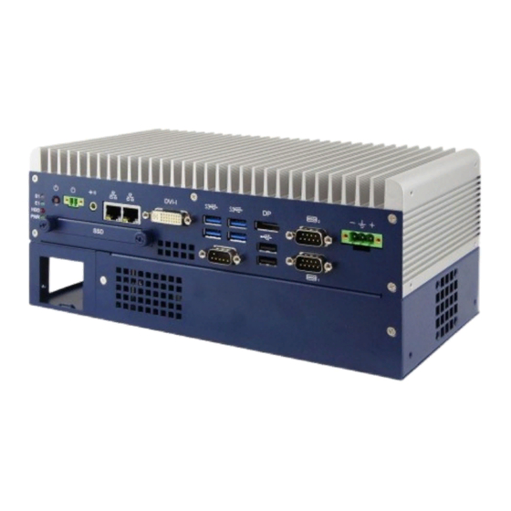
TPC-7000 User Manual 1.3. Overview Oblique View Rear View Name Name LED Indicator COM Ports (from top to bottom: S1*, E1*, (COM1 RS-232/422/485, SSD/HDD, Power) COM2 RS-232) Power Button DC-In Power Connector (3 pins) Terminal Block for Remote Power USB 2.0 Ports Button (2 pins) Audio Jack for Line-Out Reserved for Motionnet or RS-232 Port... - Page 11 TPC-7000 User Manual Wall Mount Side Mount DIN Rail Mount...
-
Page 12: Dimension
TPC-7000 User Manual 1.4. Dimension Unit: mm... -
Page 13: Hardware Configuration
TPC-7000 User Manual 2. Hardware Configuration 2.1. Installation / Replacement You need to take away the device bottom cover for the installation / replacement of memory module cards, CPU, and expansion cards except for the 1 SSD/HDD. After installations, secure the device bottom cover back. -
Page 14: Ssd/Hdd Installation Or Replacement
TPC-7000 User Manual To remove the module, press the ejector tabs outwards with your fingertips to eject the module. 2.1.2. SSD/HDD Installation or Replacement To install or replace the SSD/HDD, follow the instructions below for installation. SSD/HDD: 1. Release 2 screws to pull out the SSD/HDD tray. 1. - Page 15 SSD/HDD onto the bracket, secure it with 4 screws as pointed by arrows below. 4. Then secure the bracket and put the tray back to the device. Note: The screws and cables for the 2 SSD/HDD can be optionally purchased from TPM.
-
Page 16: Mini-Pcie Network Cards Installation Or Replacement
TPC-7000 User Manual 2.1.3. Mini-PCIe Network Cards Installation or Replacement After removing the bottom cover, follow the instructions 1. Remove the SSD/HDD tray by releasing 2 screws below. 2. Take away the expansion bracket by releasing the 8 screws below. 3. -
Page 17: Expansion Card Installation Or Replacement
TPC-7000 User Manual 2.1.4. Expansion Card Installation or Replacement 1. After removing the device bottom cover, loosen two screws below to remove the cable organizer. 2. Remove the expansion slot fillers by releasing the two screws below. 3. Install the expansion cards and fix with the screws mentioned in step 2. Then secure the cable organizer back. -
Page 18: Mounting Installation
TPC-7000 User Manual 2.1.5. Mounting Installation Note: Before mounting the system on wall, ensure that you are following all applicable building and electric codes. Requirements: Before mounting the brackets, ensure that you have enough room for power and signal cable routing. - Page 19 TPC-7000 User Manual 2.1.6.1. Side-Mounting Installation (Optional) 7. Attach the mounting bracket to your product, and secure with the supplied 4 screws. 8. Prepare at least 4 screws (M3) to install the device on wall .
-
Page 20: Din Rail Mounting Installation (Optional)
TPC-7000 User Manual 2.1.6. DIN Rail Mounting Installation (Optional) 9. Attach the DIN rail mounting bracket to your product, and secure with the supplied screws. Secure with 2 screws for a general bracket. Secure with 4 screws for a rotatable bracket. 10. -
Page 21: Pinout For Com Ports, Dc-In & Power Button Connectors
TPC-7000 User Manual 2.1.7. Pinout for COM Ports, DC-In & Power Button Connectors • COM1 RS232/422/485 Port COM1 port is jumperless and configurable in BIOS. Assigment Assigment DCD, Data carrier detect DSR, Data set ready RXD, Receive data RTS, Request to send TXD, Transmit data CTS, Clear to send DTR, Data terminal ready... - Page 22 TPC-7000 User Manual • COM2 RS-232 Port Assigment Assigment DCD, Data carrier detect DSR, Data set ready RXD, Receive data RTS, Request to send TXD, Transmit data CTS, Clear to send DTR, Data terminal ready RI, Ring indicator Ground • DC-In Power Connector (3-pin terminal block) Assigment Assigment...
-
Page 23: Motionnet Introduction
TPC-7000 User Manual 3. Motionnet Introduction 3.1. What Is Motionnet? Motionnet is a super high-speed serial communication system. The G9000 devices provide input/output control, motor control, CPU emulation and message communication with high speed serial communications (up to 20Mbps) all of which are required by current Factory Automation techniques. Motionnet always transfers 4 bytes of data in 15.1μsec using cyclic communication to control input and output. -
Page 24: Advantage Of Motionnet
TPC-7000 User Manual ports (2048 points), motion control of up to 64 axes, and LSI control of up to 128 devices. ⚫ Input/output and status communication time for each device when inputting/outputting and reading status data for each device, the system automatically refreshes the center device RAM each communication cycle. - Page 25 TPC-7000 User Manual ⚫ In cyclic communication, a communication cycle is as follows when a 20 Mbps speed is selected. Number of local Communication Remarks devices cycle 0.12 ms If all of the local devices connected are I/O devices, 256 input/output points can be used.
-
Page 26: Motionnet Product Family
TPC-7000 User Manual 3.4. Motionnet Product Family Figure 3-2: Motionnet product family... -
Page 27: Project Encryption
SmartPAC as the base system to develop applications for their customers. However, customers could find the top source vendor which is TPM and perhaps, the worst case, clone the storage in the system and purchase extra systems from TPM directly. In case of customers bypass the original system provider, which would cut down benefits for the system integrators cooperating with TPM, SmartPAC introduces a method called project encryption. - Page 28 TPC-7000 User Manual Figure 4-1: generation of the registration key From the above figure, the hardware id is obtainable within SmartPAC, taken as the content for AES algorithm. The SI key, hard coded by the system integrator, is the key to calculate the output value, the registration key.
-
Page 29: Bios Setup
TPC-7000 User Manual 5. BIOS Setup 5.1. Introduction The BIOS (Basic Input/Output System) installed in the ROM of your computer system supports Intel® processors. The BIOS provides critical low-level support for standard devices such as disk drives, serial ports and parallel ports. It also provides password protection as well as special support for detailed fine-tuning of the chipset controlling the entire system. -
Page 30: Main Settings
TPC-7000 User Manual 5.3. Main Settings BIOS Setting Description System Date Sets the date. Use the <Tab> key to switch between the data elements. System Time Set the time. Use the <Tab> key to switch between the data elements. -
Page 31: Advanced Settings
TPC-7000 User Manual 5.4. Advanced Settings This section allows you to configure, improve your system and allows you to set up some system features according to your preference. BIOS Setting Description CPU Configuration Displays CPU configuration parameters. Power & Performance Shows power and performance options. -
Page 32: Cpu Configuration
TPC-7000 User Manual 5.5. CPU Configuration BIOS Setting Description Intel (VMX) Virtualization Enables / Disables a VMM can utilize the Technology additional hardware capabilities provided by Vanderpool Technology. Active Processor Cores Number of cores to enable in each processor package. Options: All, 1, 2, 3 Enables / Disables AES (Advanced Encryption Standard). -
Page 33: Power & Performance
TPC-7000 User Manual Power & Performance 5.5.1. BIOS Setting Description Intel(R) SpeedStep(tm) Allows more than two frequency ranges to be supported. Intel(R) Speed Shift Enables / Disables the support of Intel(R) Technology Speed Shift Technology. Enabling the function will expose the CPPC v2 interface to allow for hardware controlled P-states. -
Page 34: Pch-Fw Configuration
TPC-7000 User Manual PCH-FW Configuration 5.5.2. BIOS Setting Description AMT BIOS Features When disabled AMT BIOS features are no longer supported and user is no longer able to access MEBx Setup. Note: This option does not disable manageability features in FW. -
Page 35: Acpi Settings
TPC-7000 User Manual 5.5.3. ACPI Settings BIOS Setting Description Enable Hibernation Enables / Disables the system ability to hibernate (OS/S4 Sleep State). This option may not be effective with some OS. ACPI Sleep State Selects a ACPI sleep state for the system to enter. -
Page 36: Ismart Controller
TPC-7000 User Manual iSmart Controller 5.5.4. BIOS Setting Description Power-On after Power Enables / Disables the system to be turned on failure automatically after a power failure. Temperature Guardian Generate the reset signal when system hands up on POST. Schedule Slot 1 / 2 Sets up the hour / minute / day for the power- on schedule for the system. -
Page 37: F81846 Super Io Configuration
TPC-7000 User Manual F81846 Super IO Configuration 5.5.5. BIOS Setting Description Serial Port Configuration Sets Parameters of Serial Ports. You can enable / disable the serial port and select an optimal settings for the Super IO device. -
Page 38: Serial Port 1 Configuration
TPC-7000 User Manual Serial Port 1 Configuration 5.5.6. BIOS Setting Description Serial Port Enables / Disables serial port (COM). Change Settings Selects an optimal settings for Super I/O device. Options: Auto • IO = 3F8h; IRQ = 4 • IO = 3F8h; IRQ = 3, 4, 5, 6, 7, 9, 10, 11, 12 •... -
Page 39: Serial Port 2 Configuration
TPC-7000 User Manual Serial Port 2 Configuration 5.5.7. BIOS Setting Description Serial Port Enables / Disables serial port (COM). Change Settings Selects an optimal settings for Super I/O device. Options: Auto • IO = 2F8h; IRQ = 4 • IO = 3F8h; IRQ = 3, 4, 5, 6, 7, 9, 10, 11, 12 •... -
Page 40: Serial Port 3 Configuration
TPC-7000 User Manual Serial Port 3 Configuration 5.5.8. BIOS Setting Description Serial Port Enables / Disables serial port (COM). Change Settings Selects an optimal settings for Super I/O device. Options: Auto • IO = 3E8h; IRQ = 7 • IO = 3E8h; IRQ = 3, 4, 5, 6, 7, 9, 10, 11, 12 •... -
Page 41: Serial Port 4 Configuration
TPC-7000 User Manual Serial Port 4 Configuration 5.5.9. BIOS Setting Description Serial Port Enables / Disables serial port (COM). Change Settings Selects an optimal settings for Super I/O device. Options: Auto • IO = 2E8h; IRQ = 7 • IO = 3E8h; IRQ = 3, 4, 5, 6, 7, 9, 10, 11, 12 •... -
Page 42: F81846 Hardware Monitor
TPC-7000 User Manual F81846 Hardware Monitor 5.5.10. BIOS Setting Description SYS_FAN1 Smart Fan Controls the system fan temperature by setting Control up a threashold temperature. Options: Disabled (default),. 50°C, 60°C, 70°C, 80°C SYS_R_FAN1 Smart Fan Controls the system fan temperature by setting Control up a threashold temperature. - Page 43 TPC-7000 User Manual Options: Disabled (default),. 70°C, 75°C, 80°C, 85°C, 90°C, 95°C...
-
Page 44: Csm Configuration
TPC-7000 User Manual CSM Configuration 5.5.11. BIOS Setting Description Network Controls the execution of UEFI and Legacy PXE OpROM. -
Page 45: Usb Configuration
TPC-7000 User Manual USB Configuration 5.5.12. BIOS Setting Description Legacy USB Support Enables / Disables Legacy USB support. Auto disables legacy support if there is no • USB device connected. Disable keeps USB devices available only • for EFI applications. XHCI Hand-pff This is a workaround for OSes without XHCI hand-off support. - Page 46 TPC-7000 User Manual BIOS Setting Description Device power-up delay The maximum time the device will take before it properly reports itself to the Host Controller. Auto uses default value. For a Root port, it is 100 ms. For a Hub port, the delay is taken from Hub descriptor.
-
Page 47: Chipset Settings
TPC-7000 User Manual 5.6. Chipset Settings BIOS Setting Description System Agent (SA) System Agent (SA) parameters Configuration VT-d Enables / Disables VT-d capability. -
Page 48: Pch-Io Configuration
TPC-7000 User Manual PCH-IO Configuration 5.6.1. BIOS Setting Description SATA and RST SATA device options and settings Configuration PCH LAN Controller Enables / Disables onboard NIC. Wake on LAN Enable Enables / Disables integrated LAN to wake the system. -
Page 49: Sata And Rst Configuration
TPC-7000 User Manual SATA and RST Configuration 5.6.2. BIOS Setting Description SATA Controller(s) Enables / Disables the Serial ATA. SATA Mode Selection Determines how SATA controller(s) works. AHCI Mode or Intel RST Premium. Serial ATA Port 0~2 Enables / Disables Serial Port 0 ~ 2. -
Page 50: Security Settings
TPC-7000 User Manual 5.6.3. Security Settings BIOS Setting Description Administrator Password Sets an administrator password for the setup utility. User Password Sets a user password. -
Page 51: Boot Settings
TPC-7000 User Manual Boot Settings 5.6.4. BIOS Setting Description Setup Prompt Timeout Number of seconds to wait for setup activation key. 65535 (0xFFFF) means indefinite waiting. Bootup NumLock State Selects the keyboard NumLock state. Quiet Boot Enables / Disables Quiet Boot option. Fast Boot Enables / Disables boot with initialization of a minimal set of devices required to launch the... -
Page 52: Save & Exit Settings
TPC-7000 User Manual 5.7. Save & Exit Settings BIOS Setting Description Save Changes and Exit Exits system setup after saving the changes. Discard Changes and Exits system setup without saving any changes. Exit Save Changes and Reset Resets the system after saving the changes. Discard Changes and Resets system setup without saving any Reset...
Need help?
Do you have a question about the TPC-7000 Series and is the answer not in the manual?
Questions and answers