Table of Contents
Advertisement
TABLE OF CONTENTS
GENERAL
Abbreviations
Conversion Factors
Temperature Conversion Table
General Airplane Description
Airplane Dimension Schematic
Dimensions and General Data
Overall dimension
Wing
Spar locations
Horizontal tail surface
Vertical tail surface
Fuselage
Landing gear
Areas
Doors
Baggage compartment door (LH, aft)
Antenna Location Schematic
Visual Eye References For Ground Operation
Steering Radii
Steering Radii Schematic
Turning Radii
Turning Radii Schematic
Jet Exhaust Single Engine Ground Idle Thrust
Jet Exhaust Single Engine Take-off Thrust
Jet Exhaust Two Engine Ground Idle Thrust
Jet Exhaust Two Engine Take-off Thrust
Airplane Jacking
Jacking Points Schematic
Towing
Tow Bar Attachment Schematic
Towbarless Schematic
Ground Locking Safety Pins
Mooring
Rev 12, Aug 14, 2006
AIRPLANE GENERAL
TABLE OF CONTENTS
CHAPTER 1
Flight Crew Operating Manual
CSP 700−5000−6
Page
01−00−1
01−10−1
01−10−13
01−10−14
01−10−15
01−10−16
01−10−17
01−10−17
01−10−17
01−10−17
01−10−17
01−10−17
01−10−17
01−10−17
01−10−18
01−10−18
01−10−18
01−10−19
01−10−20
01−10−21
01−10−21
01−10−22
01−10−22
01−10−23
01−10−24
01−10−25
01−10−26
01−10−27
01−10−27
01−10−28
01−10−28
01−10−29
01−10−29
01−10−30
Volume 2
01−00−1
Advertisement
Table of Contents

Subscribe to Our Youtube Channel
Related Manuals for BOMBARDIER GLOBAL 5000


Summary of Contents for BOMBARDIER GLOBAL 5000
- Page 1 AIRPLANE GENERAL TABLE OF CONTENTS CHAPTER 1 Page TABLE OF CONTENTS 01−00−1 GENERAL Abbreviations 01−10−1 Conversion Factors 01−10−13 Temperature Conversion Table 01−10−14 General Airplane Description 01−10−15 Airplane Dimension Schematic 01−10−16 Dimensions and General Data 01−10−17 Overall dimension 01−10−17 Wing 01−10−17 Spar locations 01−10−17 Horizontal tail surface...
- Page 2 AIRPLANE GENERAL TABLE OF CONTENTS Page GENERAL Mooring Attachment Points Schematic 01−10−30 Seat Assembly 01−10−31 Seat Egression 01−10−32 Moving the Seat Forward 01−10−32 Eye Locator−Seat Adjustment 01−10−33 Control Wheel 01−10−34 Master Disconnect 01−10−34 Pitch Trim Switch 01−10−34 Autopilot/Flight Director (Touch Control) 01−10−34 Radio Transmit Switch 01−10−34...
-
Page 3: Table Of Contents
AIRPLANE GENERAL TABLE OF CONTENTS Page GENERAL Internal Door Operation 01−10−52 Manual Closing 01−10−52 Emergency Exit 01−10−53 Aft Equipment Bay Door 01−10−55 Aft Equipment Bay Door Schematic 01−10−55 Aft Equipment Bay Door Operation 01−10−56 Baggage Compartment Door 01−10−57 Baggage Door Operation 01−10−58 Baggage Door Indication 01−10−58... - Page 4 AIRPLANE GENERAL TABLE OF CONTENTS THIS PAGE INTENTIONALLY LEFT BLANK Volume 2 Rev 2A, Apr 11, 2005 Flight Crew Operating Manual 01−00−4 CSP 700−5000−6...
- Page 5 AIRPLANE GENERAL ABBREVIATIONS The following abbreviations may be used by cockpit displays, radio tuning units and flight management system or be found throughout the manual. Some abbreviations may also appear in lower case letters. Abbreviations having very limited usage are explained in the systems chapters where they are used.
- Page 6 AIRPLANE GENERAL ABBREVIATIONS (CONT'D) B/AIR Bleed Air Bleed Bleed Management B/C, BC Back Course Controller B/CRS Back Course BOOM Headset microphone Brake Control Unit Bearing B/LEAK Bleed Leak BRKR(s) Breaker(s) BARO Barometric Bright Battery Bottle BATT Battery BTMS Brake Temperature Bearing Distance Indicator Monitoring System Built-In-Test...
- Page 7 AIRPLANE GENERAL ABBREVIATIONS (CONT'D) CPAM Cabin Pressure Acquisition Cathode Ray Tube Module Cruise CPCP Cabin Pressure Control Center Panel CPCS Cabin Pressure Control Cabin Pressure Controller System CPCS Cabin Pressure Control CTRL Control System Cockpit Voice Recorder Couple Clockwise CPLT Copilot Cylinder Course...
- Page 8 AIRPLANE GENERAL ABBREVIATIONS (CONT'D) EICAS Engine Indication and Crew Engine Pressure Ratio Alerting System EQUIP Equipment Elevation Eye Reference Position ELEC Electrical (datum) ELEV Elevator, Elevation Essential Emergency Locator Elapsed Time Transmitter Estimated Time of Arrival EMER(G) Emergency ETTC Essential TRU Tie Contactor Electrical Management ETOPS Extended Range Twin...
- Page 9 AIRPLANE GENERAL ABBREVIATIONS (CONT'D) G (+/−) Receiver Gain Ground Gallons Per Minute Glideslope Go-around GPWS Ground Proximity Warning System Gallon Gear GALY Galley Gravity Ground Clutter Suppression GS,G/S Glideslope Generator Control Unit Ground Speed General Electric Generator Transfer Generator Contactor Generator Line Contactor Guidance Panel Ground Lift Dumper (ing)
- Page 10 AIRPLANE GENERAL ABBREVIATIONS (CONT'D) IMBAL Imbalance INST(S) Instrument(s) Instrument Meteorological INST, INSTR Instrument Conditions Internal, Integral, Intersection Imperial INTEG Integral Inch, Inches Input/Output IN Hg Inches of Mercury Inertial Reference System INBD Inboard Inertial Reference Unit INCR Increase International Standard Indication, Indicator Atmosphere INFLT...
- Page 11 AIRPLANE GENERAL ABBREVIATIONS (CONT'D) Lo Pressure Turbine LTG(s) Light(s) Left Rear Left Wing Long Range Cruise Left Wing Down Long Range Navigation Lower Lower Side Band Mach Number Miles Meter Microphone Maximum Authorized IFR MID AFT Middle Aftward Altitude MID FWD Middle Forward Mean Aerodynamic Chord MILS...
- Page 12 AIRPLANE GENERAL ABBREVIATIONS (CONT'D) Not Applicable Nose Left Nose Landing Gear High Pressure Rotor RPM Navigation Nautical Mile(s) Nose Down, Navigation Number Display NOPT No Procedure Turn Required NDB (ADF) Nondirectional Beacon NORM Normal (Automatic Direction Finder) NOSE, N/W Nose Wheel Negative Nose Right NEUT...
- Page 13 AIRPLANE GENERAL ABBREVIATIONS (CONT'D) Quick Access Recorder Altimeter Setting Quantity Quick Engine Change Local Station Pressure Right REFL Refuel Radio Altitude Reverse Resolution Advisory (TCAS) Right Hand Ram Air Turbine Radio Magnetic Indicator RAT GEN Ram Air Turbine Generator Radio Management Unit RATLC Ram Air Turbine Line Rotation...
- Page 14 AIRPLANE GENERAL ABBREVIATIONS (CONT'D) STAB Stabilizer Synchronize STAT Status SYNC Synchronous STEER Steering SYS, SYST System SUPPL Supply Standard SW(s) Switches Traffic Advisory (TCAS) TRU Line Contactor TACAN UHF Tactical Air Navigation Thermal Management System True Airspeed TO, T/O Take-off Total Air Temperature Tolerance TCAS...
- Page 15 AIRPLANE GENERAL ABBREVIATIONS (CONT'D) Stalling Speed or the Variable Frequency Minimum Steady Flight Generator Speed at which the Airplane Visual Flight Rules is Controllable Vertical Gyro Stalling Speed or the Very High Frequency Minimum Steady Flight (30 − 300 MHz) Speed in the Landing Vibration Configuration...
- Page 16 AIRPLANE GENERAL ABBREVIATIONS (CONT'D) YD, Y/D Yaw Damper Zero Fuel Weight Volume 2 Rev 2A, Apr 11, 2005 Flight Crew Operating Manual 01−10−12 CSP 700−5000−6...
- Page 17 AIRPLANE GENERAL CONVERSION FACTORS Km/hr 0.54 knots Multiply To Obtain 0.6214 Centimeters 0.3937 Knots 1.151 1.852 km/hr Centimeters² 0.155 in² 0.145 Centimeters³ 0.061 in³ Liters 0.2642 0.22 Imperial gal Cu ft³ 0.0283 meters³ Meters 3.281 0.3048 meters Meters² 10.76 ft² Ft²...
- Page 18 AIRPLANE GENERAL TEMPERATURE CONVERSION TABLE °C °F °C °F °C °F °C °F °C °F °C °F °C °F °C °F °C °F °C °F °C °F °C °F −73.3 −100 −148.0 −45.6 −50 −58.0 −17.8 32.0 10.0 122.0 37.8 212.0 65.6 302.0...
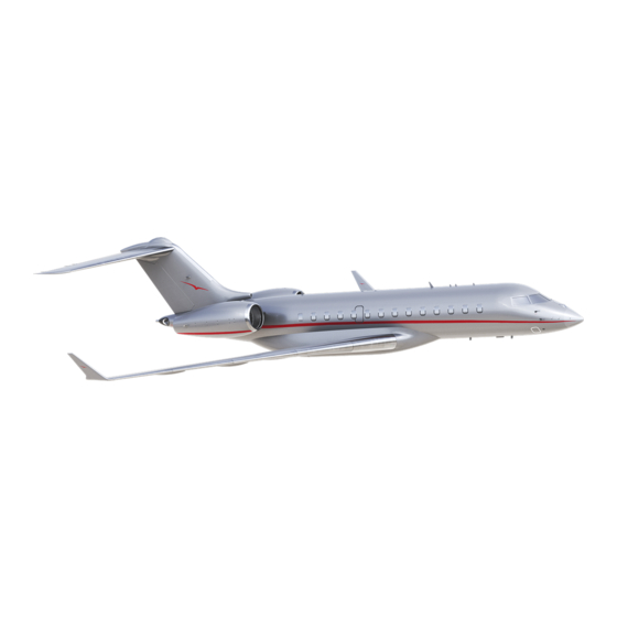
- Page 19 AIRPLANE GENERAL GENERAL AIRPLANE DESCRIPTION The airplane is a swept-wing monoplane with a pressurized cabin. It is capable of accommodating a pilot, a copilot, a third crew member and up to 19 passengers. The airplane has two BMW/Rolls Royce BR 710 turbofan engines. The airplane structure, in general, is fabricated from aluminum alloys.
- Page 20 AIRPLANE GENERAL AIRPLANE DIMENSION SCHEMATIC (3.07 m) 13 ft 4 in (4.06 m) 94 ft 0 in (28.65 m) 8 ft 10 in (2.70 m) 42 ft 7 in (12.98 m) 25 ft 6 in (7.77 m) 83 ft 9 in (25.53 m) 96 ft 9 in (29.49 m)
- Page 21 AIRPLANE GENERAL DIMENSIONS AND GENERAL DATA The data that follows is for general information only and is not to be used for inspection or rejection purposes. When specific data is required, the applicable illustration should be used. Overall dimension Length 96 ft.
- Page 22 AIRPLANE GENERAL DIMENSIONS AND GENERAL DATA (CONT'D) Landing gear (Cont’d) Tire size 38 in. 21 in. Max loaded tire pressure 172 psi. 154 psi Main gear track 13 ft. 8 in. (4.18 m) Nose gear track 13.14 in. (33.4 cm) Wheel base (max.) 40 ft.
- Page 23 AIRPLANE GENERAL ANTENNA LOCATION SCHEMATIC SATCOM (If installed) VHF COMM #1 VHF COMM #3 VOR/LOC (LH AND RH) MODE ADF #2 MODE ADF #1 TCAS (Directional) GPS #1 RAD ALT #2 RX RAD ALT TCAS #1 RX OMNI RAD ALT MODE S #1 TX RAD ALT...
- Page 24 AIRPLANE GENERAL VISUAL EYE REFERENCES FOR GROUND OPERATION Volume 2 Rev 3, Apr 25, 2005 Flight Crew Operating Manual 01−10−20 CSP 700−5000−6...
- Page 25 AIRPLANE GENERAL STEERING RADII Steering radii are shown below. STEERING RADII SCHEMATIC 40 ft 4 in (12.30 m) 128 ft 2 in 56 ft 6 in (39.07 m) (17.24 m) 7 ft 4 in (2.3 m) 14 ft 0 in (4.26 m) 20 ft 8 in (4.23 m)
- Page 26 AIRPLANE GENERAL TURNING RADII Minimum paving width for 180° turn − 65 ft. (19.92 m) TURNING RADII SCHEMATIC Volume 2 Rev 3, Apr 25, 2005 Flight Crew Operating Manual 01−10−22 CSP 700−5000−6...
- Page 27 AIRPLANE GENERAL JET EXHAUST SINGLE ENGINE GROUND IDLE THRUST Volume 2 Rev 3, Apr 25, 2005 Flight Crew Operating Manual 01−10−23 CSP 700−5000−6...
- Page 28 AIRPLANE GENERAL JET EXHAUST SINGLE ENGINE TAKE-OFF THRUST Volume 2 Rev 3, Apr 25, 2005 Flight Crew Operating Manual 01−10−24 CSP 700−5000−6...
- Page 29 AIRPLANE GENERAL JET EXHAUST TWO ENGINE GROUND IDLE THRUST Volume 2 Rev 3, Apr 25, 2005 Flight Crew Operating Manual 01−10−25 CSP 700−5000−6...
- Page 30 AIRPLANE GENERAL JET EXHAUST TWO ENGINE TAKE-OFF THRUST Volume 2 Rev 3, Apr 25, 2005 Flight Crew Operating Manual 01−10−26 CSP 700−5000−6...
- Page 31 AIRPLANE GENERAL AIRPLANE JACKING Three jacking points are provided, one on the forward fuselage and one on each wing rear spar for jacking the complete airplane. JACKING POINTS SCHEMATIC SUPPORT BEAM JACKING POINT JACK PAD NYLON PLUG TYPICAL JACK LEGEND JACK REAR FUSELAGE SUPPORT REAR FUSELAGE SUPPORT...
- Page 32 AIRPLANE GENERAL TOWING A fitting for towing or pushing the airplane is located on the nose landing gear. During towing, nose wheel swivel through the range of ±75° each side of center is possible, without disconnecting the nose wheel steering torque links. The Aircraft Maintenance Manual (Chapter 09) has a detailed description of towing operations.
- Page 33 AIRPLANE GENERAL TOWBARLESS SCHEMATIC WINCH STRAP TOWBARLESS TOW VEHICLE WINCH CUT−OFF SWITCH PLATE STRUT−STRAP NOSE LANDING GEAR CRADLE REAR GATE Ground Locking Safety Pins Ground safety locks are provided for the nose and each main gear, gear doors and for the Ram Air Turbine (RAT).
- Page 34 AIRPLANE GENERAL MOORING Fittings are provided on the fuselage and on the wing jacking points for mooring the airplane. Mooring procedures are located in the Aircraft Maintenance Manual (Chapter 10). MOORING ATTACHMENT POINTS SCHEMATIC MOORING ADAPTER PLATE MAIN AND NOSE AREAS JACKING PAD TAIL AREA TIE DOWN RING...
- Page 35 AIRPLANE GENERAL SEAT ASSEMBLY The crew seats provide adjustments fore and aft, inboard/outboard lateral adjustment (“J” track), height and armrest position. Volume 2 Rev 12, Aug 14, 2006 Flight Crew Operating Manual 01−10−31 CSP 700−5000−6...
- Page 36 AIRPLANE GENERAL SEAT ASSEMBLY (CONT'D) Seat Egression Make sure the seat is in the fully upright position, then pull on the fore/aft lever and move the seat to its fully aft position. NOTE The lateral tracking is now automatically enabled. CAUTION Do not try to move the seat laterally with the fore/aft lever in the up position.
- Page 37 AIRPLANE GENERAL EYE LOCATOR-SEAT ADJUSTMENT An eye locator is mounted on the centre windshield post to enable seat adjustment for correct eye-to-wheel height. TOP VIEW FRONT VIEW NOTE The support bracket is not shown. Volume 2 Rev 12, Aug 14, 2006 Flight Crew Operating Manual 01−10−33 CSP 700−5000−6...
- Page 38 AIRPLANE GENERAL CONTROL WHEEL The pilot and copilot control wheels contain the following switches: • Master disconnect. • Pitch Trim Switch. • Autopilot/Flight Director Touch Control. • Radio Key. Master Disconnect The Master Disconnect switch disengages the autopilot, deactivates the stick pusher and the pitch trim.
- Page 39 AIRPLANE GENERAL FLIGHT COMPARTMENT GENERAL ARRANGEMENT DISCH DISCH DISCH PULL PULL PULL TEMPERATURE COCKPIT FWD CABIN AFT CABIN COLD COLD COLD RAM AIR RECIRC TRIM AIR AURAL WARNING IAC 1 IAC 2 AUX PRESS MUTED MUTED L MAN R MAN PRESSURIZATION AUTO TEMP...
- Page 40 AIRPLANE GENERAL FLIGHT COMPARTMENT (AFT VIEW) OIL REPLENISHMENT POWER SYSTEM RESERVOIR LH ENG RH ENG TANK PUMP OPEN OPEN OPEN PRINT MAINT REPORT REFUEL/DEFUEL PANEL PRESEL INCR LEFT CENTER RIGHT DATA UPLOAD/DOWNLOAD DECR DAU 1A TOTAL PRESEL DAU 1B IAC 1 MANUAL AUTO DAU 2A...
- Page 41 AIRPLANE GENERAL PILOT'S SIDE CONSOLE FLASHLIGHT HEADSET PANEL FROM SYSTEM SELECT RESET TEST OXYGEN MASK PUSH 100% FLASHLIGHT HEADSET HDPH 1. Oxygen Mask/Regulator 2. Headset Panel 3. Navigation Display Unit 4. Nosewheel Steering Handwheel Indicates Chapter in which information on item may be found. Volume 2 Rev 12, Aug 14, 2006 Flight Crew Operating Manual...
- Page 42 AIRPLANE GENERAL PILOT'S SIDE PANEL STALL PUSHER DT GPS INT MODE CIRCUIT BREAKER − SYSTEM 1/2 AFCS DOORS AIR COND/PRESS ELEC ENGINE BLEED FIRE CAIMS FLT CONTROLS COMM FUEL 1. Electrical Management System 2. Stall Pusher Switch 3. Clock 4. Air Conditioning Gasper Indicates Chapter in which information on item may be found.
- Page 43 AIRPLANE GENERAL PILOT'S INSTRUMENT PANEL LNAV AP1 VALT VAPP VNAV KPHX KLAX KSRP KDVT 29.92 12.5 KDVT 1+36 KPHX −56 −40 KDVT KSRP FL180 GSPD 4000 4000 TERR AIRSPEED LIMITS − (INDICATED SPEEDS) VFE (SLATS OUT, 0° FLAPS)....225 VMO (BELOW 8,000 FT)...... 300 VFE (SLATS OUT, 6°...
- Page 44 AIRPLANE GENERAL CENTRE INSTRUMENT PANELS Standby Attitude Indicator CKPT (°C) CAB ALT 1300 1.65 1.65 CABIN (°C) CABIN (°C) 1.54 1.54 0.00 CAB RATE OXYGEN OUTFLOW VALVES 73.3 73.3 OPEN OPEN OIL QTY (QTS) 10.4 10.4 0 1 3 93.4 93.4 BRAKE TEMP mb/hPa...
- Page 45 AIRPLANE GENERAL OVERHEAD PANEL DISCH DISCH DISCH PULL PULL PULL TEMPERATURE COCKPIT FWD CABIN AFT CABIN COLD COLD COLD RAM AIR RECIRC TRIM AIR AURAL WARNING IAC 1 IAC 2 AUX PRESS MUTED MUTED PRESSURIZATION AUTO L MAN R MAN TEMP TEMP AUTO/...
- Page 46 AIRPLANE GENERAL GLARESHIELD MASTER WARNING/CAUTION MINIMUMS NAV SCR BARO SET ROLL SPLRS BARO WARNING ROLL CAUTION ROLL PLT CONT PUSH STD Left Glareshield CRS 1 CRS 1 PUSH SYNC PUSH DCT PUSH CHG PUSH DCT Centre Glareshield MASTER WARNING/CAUTION MINIMUMS NAV SCR BARO SET ROLL SPLRS...
- Page 47 AIRPLANE GENERAL CENTRE PEDESTAL EGPWS MUTED OVRD NOSE STEER LDG GEAR HORN PILOT EVENT GND LIFT AUTO BRAKE DUMPING ENGINE COM1 NAV1 COM1 NAV1 118.00 131.10 118.00 131.10 131.27 112.00 131.27 112.00 MEMORY−1 TEMP−1 MEMORY−1 TEMP−1 ATC/TCAS ADF1 ATC/TCAS ADF1 1605 620.0 1605...
- Page 48 AIRPLANE GENERAL COPILOT'S INSTRUMENT PANEL LNAV AP1 VALT VAPP VNAV KPHX KLAX KSRP KDVT 29.92 12.5 KDVT 1+36 KPHX −56 −40 KDVT KSRP FL180 GSPD 4000 4000 TERR AIRSPEED LIMITS − (INDICATED SPEEDS) VFE (SLATS OUT, 0° FLAPS)....225 VMO (BELOW 8,000 FT)...... 300 VFE (SLATS OUT, 6°...
- Page 49 AIRPLANE GENERAL COPILOT'S SIDE PANEL STALL PUSHER DT GPS INT MODE CIRCUIT BREAKER − SYSTEM 1/2 AFCS DOORS AIR COND/PRESS ELEC ENGINE BLEED FIRE CAIMS FLT CONTROLS COMM FUEL 1. Electrical Management System 2. Stall Pusher Switch 3. Clock 4. Air Conditioning Gasper Indicates Chapter in which information on item may be found.
- Page 50 AIRPLANE GENERAL COPILOT'S SIDE CONSOLE PITOT STATIC SELECT VALVE SELECT VALVE CLOSED CLOSED RESET TEST OXYGEN MASK PUSH 100% PASSENGER OXYGEN FLASHLIGHT NORMAL TEST PORT CLOSED OVERRIDE FIRST AID PASS ON COCKPIT VOICE RECORDER MICROPHONE MONITOR ERASE TEST STATUS HEADPHONE HEADSET HDPH 1.
- Page 51 AIRPLANE GENERAL AIRPLANE DOORS The airplane is equipped with the one passenger door (which serves as an emergency exit), one overwing emergency exit, one baggage compartment door, one rear fuselage equipment bay door and several service doors and panels. The door warning system provides the flight crew with a visual indication (EICAS), when any of the following exterior doors/exits are opened or incorrectly latched: •...
- Page 52 AIRPLANE GENERAL PASSENGER DOOR SCHEMATIC CABLE ASSEMBLY HANDRAIL ASSEMBLY CLOSED POSITION PASSENGER DOOR COMPONENTS The following components are described to provide an understanding of the passenger door operating system. Airstair and Handrails Assembly The airstairs act as the steps for embarking/disembarking the airplane. They also act as support for the door structure, which hangs below the airstairs when open.
- Page 53 AIRPLANE GENERAL PASSENGER DOOR COMPONENTS (CONT'D) Lift arms Two levers are connected from either end of the lockshaft to the fixed linked arms on the airstair structure. They are driven by the handles, assisted by the tension spring. Their purpose is to lift the door out of its frame and hold it up and out in relation to the airstair, while the door is opening.
- Page 54 AIRPLANE GENERAL PASSENGER DOOR OPERATING HANDLES The external handle is set into a box in the lower door structure. It is connected by push/pull rods inside the door to the lockshaft, at the forward end. EXTERNAL HANDLE LOCKSHAFT NOTE The door is not in the fully closed position until the handle moves to the full down position.
- Page 55 AIRPLANE GENERAL PASSENGER DOOR SWITCHES The internal door operating switch is controlled on and off by the “DOOR” switch installed internally in the door frame, next to the main passenger door. NOTE Both switches are guarded but not shown. EXTERNAL SWITCH INTERNAL SWITCH (view looking from inside the airplane)
-
Page 56: Internal Door Operation 01−10−52
AIRPLANE GENERAL PASSENGER DOOR OPERATION The following examples are intended to familiarize the operator with events which occur when moving the passenger door from either the open or closed positions. The door operations are described in detail and should be followed as per Aircraft Maintenance Manual Chapter 52. External Door Operation To open the passenger door externally: •... -
Page 57: Emergency Exit 01−10−53
AIRPLANE GENERAL EMERGENCY EXIT An overwing emergency plug type emergency exit is installed on the right side of the airplane. The exit is an inward opening plug type and can be unlatched from the interior or exterior of the airplane. Emergency door operation from inside the cabin is achieved by single action of the emergency exit operating handle. - Page 58 AIRPLANE GENERAL EMERGENCY EXIT (CONT'D) To unlatch the emergency exit door from the interior, the upper door handle is pulled inward. This motion opens the exterior push plate/vent flap to bleed any residual pressure and disengages the two latch pins. The door moves inward and pivots on the lower hook fittings. A grip of the upper handle is maintained while grasping the lower hand grip and the door is lifted inwards away from the door opening.
-
Page 59: Aft Equipment Bay Door 01−10−55
AIRPLANE GENERAL AFT EQUIPMENT BAY DOOR The unpressurized aft equipment bay is accessed by a maintenance door in the fuselage fairing. The door is horizontally hinged at it’s forward edge with initial and subsequent opening movements being downward and outward. When the door is opened, it is restrained from over travel and striking the belly fairing using two, door-to-fairing mounted lanyards. - Page 60 AIRPLANE GENERAL AFT EQUIPMENT BAY DOOR SCHEMATIC (CONT'D) Aft Equipment Bay Door Operation DOOR OPENING − Door opening is accomplished by depressing the trigger and pulling the handle to the full open position. DOOR LATCH HANDLE ASSEMBLY DOOR CLOSING − The door latch handle is flush fitting and is secured by an integral push trigger, which when depressed, releases the handle to the free open position.
-
Page 61: Baggage Compartment Door 01−10−57
AIRPLANE GENERAL BAGGAGE COMPARTMENT DOOR A baggage compartment plug type access door is installed in the fuselage aft section on the left side forward of the rear pressure bulkhead. BAGGAGE COMPARTMENT INTERIOR CARGO DOOR Cargo OPENING Compartment DOOR HANDLE Aft Passenger Compartment Bulkhead The door is an inward opening plug type and can be unlatched from outside or inside the airplane. -
Page 62: Baggage Door Operation 01−10−58
AIRPLANE GENERAL BAGGAGE COMPARTMENT DOOR (CONT'D) A vent door is located in the upper portion of the door and will not close until the door is fully closed and the handle stowed in the locked position. VENT DOOR/SEAL INTERIOR DOOR HANDLE DETENT BUTTON Baggage Door Operation CLOSING THE BAGGAGE DOOR EXTERNALLY −... -
Page 63: Door Indication And Control 01−10−59
AIRPLANE GENERAL DOOR INDICATION AND CONTROL The airplane door position and locked indication is provided to the EICAS by the LGECU. The LGECU provides data that is used to generate alerts and synoptic displays for the fuselage doors. Door position information is displayed on the STAT page and message information is displayed on the PRIMARY page. -
Page 64: Large Maintenance Doors 01−10−60
AIRPLANE GENERAL DOOR INDICATION AND CONTROL (CONT'D) Baggage Door Two proximity sensors monitor the door position and provide signals to the LGECU which in turn provides the EICAS display. Large Maintenance Doors Two (optional third) separate large hinged and latched maintenance hatches, are monitored by the LGECU. -
Page 65: Eicas Messages 01−10−61
AIRPLANE GENERAL EICAS MESSAGES PASSENGER DOOR L−R EMER EXIT Comes on to indicate Comes on to indicate that the passenger door that the applicable is not closed and emergency exit door is locked. not in position. PASSENGER DOOR CARGO DOOR L−R EMER EXIT DOOR SYS FAIL LARGE SERV DOORS... - Page 66 AIRPLANE GENERAL THIS PAGE INTENTIONALLY LEFT BLANK Volume 2 Rev 12, Aug 14, 2006 Flight Crew Operating Manual 01−10−62 CSP 700−5000−6...
-
Page 67: Ems Circuit Protection
AIRPLANE GENERAL EMS CIRCUIT PROTECTION CB - DOORS SYSTEMS CIRCUIT BREAKER − SYSTEM 1/2 AFCS DOORS AIR COND/PRESS ELEC ENGINE BLEED FIRE CAIMS FLT CONTROLS COMM FUEL CIRCUIT BREAKER SYSTEM PREV NEXT EMER STAT CNTL TEST PAGE PAGE CNTL CB − DOORS SYSTEMS PAX DOOR MOTOR AV BATT DCPC... - Page 68 AIRPLANE GENERAL EMS CIRCUIT PROTECTION THIS PAGE INTENTIONALLY LEFT BLANK Volume 2 Rev 2A, Apr 11, 2005 Flight Crew Operating Manual 01−20−2 CSP 700−5000−6...
Need help?
Do you have a question about the GLOBAL 5000 and is the answer not in the manual?
Questions and answers