
Summary of Contents for DRYDEN AQUA FlowVis digital
- Page 1 English Rev.1.3 10/2020 FlowVis® digital OPERATING MANUAL (EN) IMPORTANT NOTE: For the most up-to-date version of this manual, please visit www.drydenaqua.com/downloads WWW.DRYDENAQUA.COM...
-
Page 2: Table Of Contents
Table of contents SECTION Description ........................3 Compatibility .........................3 Safety Information .......................3 What’s included ......................4 Dimensions ........................5 Pre-Installation .......................5 Installation ........................6 Wiring ..........................9 Output ..........................10 Programming ........................11 Operation ........................12 Advanced Setup ......................12 Auxiliary Relay .......................15 Display Features ......................16 Troubleshooting ......................17 Environmental .......................18 Standards &... -
Page 3: Description
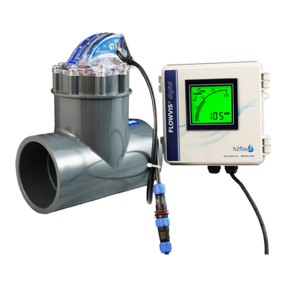
Even with the ability to install FlowVis in tight spaces and with almost zero straight pipe requirements, it can sometimes be difficult to install the device in a location that makes it easy to read. FlowVis Digital solves this problem by allowing you to install a Digital readout in a user accessible location. -
Page 4: What's Included
Fig 1.5 Type A to Type B cable Equipment and accessories not included in the FlowVis digital (FV-D) box: Fig 1.6 Optional, 8M Fig 1.7 Optional Auxiliary Fig 1.4 For 1.5”(DN40), (26.25ft.) extension cable Interface Unit 2”(DN50), 2.5”(DN65) FlowVis... -
Page 5: Dimensions
November 2020. This section covers two scenarios for installing the FlowVis Digital system: a) Install FlowVis Digital to a new OR existing FlowVis unit for 1.5”/DN40, 2”/DN50, or 2.5”/DN65 pipe. If this section applies to you, please refer to Installation section 6.1 before proceeding to Installation section 6.3. -
Page 6: Installation
DN40, DN50, and DN65, it will be necessary to replace the Flapper and its attached red indicator with the one provided in the FlowVis digital (FV-D ) packing box (see Fig.1.4 on page 4) - regardless of whether the FlowVis unit itself is new or already installed. - Page 7 FlowVis lid assembly. Place 6 of the 8 FlowVis screws in the lid assembly, and use the 2 longer screws provided with your FlowVis Digital (Fig.1.3 on page 4) in the holes for the Fig 2.5 sensor.
- Page 8 ≥ 3” (DN80), and the sensor light is flashing, it is apparent that your FlowVis unit was manufactured before this date. Please contact Dryden Aqua to find a solution. If your FlowVis model is for a 2.5” (DN65) or smaller, and the blue sensor light is flashing, please install the replacement flapper/indicator that was included in the FlowVis Digital shipping box (see section 6.1 of this document).
-
Page 9: Wiring
8. Wiring Power Supply Wiring Sensor Wiring Fig 2.7 Fig 2.8 WWW.DRYDENAQUA.COM... -
Page 10: Output
9. Output Auxiliary Relay External 4-20 mA Wiring Equipment Connection Fig 3.0 Auxiliary Relay Wiring COIL Fig 2.9 Fig 3.1... -
Page 11: Programming
10. Programming To proceed with programming, first locate the DIP switches on the back side of the Digital display. Refer to the circled area in Fig.3.2. Important Note: It is important to select the correct DIP switch position based on BOTH the model (first column) and the pipe size (second column) shown in the table below as multiple FlowVis models exist for the same pipe diameter. -
Page 12: Operation
11. Operation After setting the DIP Switches to reflect the FlowVis model and Pipe Size employed in your application, the FlowVis Digital is ready to use. No calibration or further settings are required. However, by default, the FlowVis Digital readout will display the flow rate in US GPM and the Turnover Rate will show --- (indicating that this function is not activated). - Page 13 With the Configurator program still open, connect the Display to your PC using the Type A to Type B cable that was delivered with your FlowVis Digital (Fig 1.5). The FlowVis Digital screen should display the text ‘US.b’ , and the Configurator should now look like Fig.3.6, below. Click on the ‘Configure APM’ button.
- Page 14 Advanced setup cont. You should now see a screen that looks like the one below (Fig. 3.7): In this screen, you can program: • The unit of measurement in either US GPM (default), LPM, or M • If being installed to a swimming pool, then the turnover rate by inserting the volume of your pool Please do not change any other values.
-
Page 15: Auxiliary Relay
13. Auxiliary relay (optional kit) The Auxiliary Relay option is a valuable feature that allows the FlowVis Digital user to control external devices such as Heater and Chemical Feeders at user-defined flow rates. For example, you may want to control the Chemical Feeder to operate only above 20 GPM. -
Page 16: Display Features
14. Display features The FlowVis Digital Display comprises certain standard features as well as user-defined parameters / adjustments. Standard features include a Digital and Bar Graph reading of the measured flow rate. The user has the option to program the Unit of Measurement to be displayed in either US GPM (default), LPM or M /hour. -
Page 17: Troubleshooting
14. Display features cont. On all FlowVis Digital installations for 8-inch FlowVis units, please note that the text ‘X10’ will appear above the flow reading at all times. See the below examples and instructions on how to properly read these flow rates: Note the ‘X10’... -
Page 18: Environmental
Check that the DIP switch settings applied in ‘Programming’ section, correcly related to Digital Display is reading a flow rate that is the FlowVis model being used. If applied correctly, please contact Dryden Aqua for further guidance. significantly different to... -
Page 19: Specifications
Relay Coil ..................12VDC (sourced and controlled by the Display) Analog Output (4-20mA) Scaled to ..................4 mA = zero flow, 20 mA = max flow rate limit of installed FlowVis Output Format................Voltage sourced from FlowVis Digital Display Maximum Load ................250 ohms Accuracy Flow Rate Accuracy ..............>97.9% for all FlowVis models... -
Page 20: Warranty
FlowVis Digital sensor or FlowVis lid due to the over-tightening of lid screws, damage to the FlowVis Digital LCD display...
Need help?
Do you have a question about the FlowVis digital and is the answer not in the manual?
Questions and answers