Table of Contents
Advertisement
Quick Links
Advertisement
Table of Contents

Subscribe to Our Youtube Channel
Summary of Contents for Gentec-EO OEM PCB
- Page 2 SAFETY INFORMATION Do not use the OEM PCB if the device or the detector looks damaged, or if you suspect that the OEM PCB is not operating properly. Caution: Changes or modifications not expressly approved in writing by Gentec-EO Inc.
-
Page 3: Table Of Contents
UPPLY PCB....................4 ONNECTING THE DISK TO THE ..........................4 VOIDING OISE ......................4 EMOVING THE NTICIPATION OEM PCB....................... 5 DJUSTING THE 1 ............................6 PPENDIX LIST OF ILLUSTRATIONS 1-1 T OEM PCB P OTENTIOMETER 1-2 V OEM PCB IC... -
Page 4: The Oem Pcb
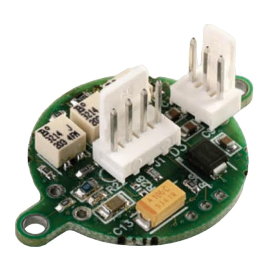
1 THE OEM PCB Introduction The OEM PCB contains 1 amplification circuit and 1 anticipation circuit. The circuits are wired in series. The OEM PCB requires only 1 single power supply. The negative power is generated on board. The OEM PCB gain is factory adjusted, but there is a potentiometer for fine tuning. -
Page 5: Power Supply
3 pin connector. If the disk is far from the PCB, it is recommended to use a shielded two wire cable, ex: Belden # “9397 black”. The output of the OEM PCB will not work in the negative input voltage. -
Page 6: Adjusting The Oem Pcb
OEM PCB Manual Revision 2.7 1.6 Adjusting the OEM PCB. The OEM PCB has 3 potentiometers: Potentiometer R7 is the offset adjustment. Potentiometer R5 is the gain adjustment. Potentiometer R6 is the anticipation adjustment. The gain is factory adjusted, but the potentiometer has a ±30% adjustment. The anticipation is factory adjusted, but the anticipation potentiometer has a ±30% adjustment. -
Page 7: Ppendix 1
OEM PCB Manual Revision 2.7 1.7 Appendix 1 Before making your cable, make sure you check the pin out of J1 because the viewing direction change the order of it. Fig 1-2 View of the OEM PCB IC side... - Page 8 OEM PCB Manual Revision 2.7 Fig 1-3 View of the OEM PCB potentiometer side.
- Page 9 OEM PCB Manual Revision 2.7 Fig 1-4 The OEM PCB...
- Page 10 OEM PCB Manual Revision 2.7...
Need help?
Do you have a question about the OEM PCB and is the answer not in the manual?
Questions and answers