
Summary of Contents for Lion Precision SPINDLECHECK
- Page 1 SPINDLECHECK INSPECTOR USER’S GUIDE Machine Tool Inspection Oakdale, MN, USA www.lionprecision.com 651-484-6544 www.lionprecision.com/two-year-warranty/ Document No. M017-7500.004...
- Page 2 This instruction manual details the operation of the Lion Precision’s SpindleCheck Machine Capability Tester system with SpindleCheck Inspector Software. Please contact us if you have any questions or suggestions on how we can be of greater service to you. Lion Precision 651-484-6544 info@lionprecision.com...
-
Page 3: Table Of Contents
TABLE OF CONTENTS INTRODUCTION Measurements Performed by SpindleCheck SpindleCheck Components COMPONENT 1 - SPINDLECHECK DEVICE ELECTRONICS Probe Connections Index Sensor (Purple) Capacitive Displacement Sensors (X, Y, Z) COMPONENT 2 - CAPACITIVE PROBES (X, Y, Z) COMPONENT 3 - EDDY CURRENT PROBE (INDEX) - Page 4 Confirm Settings Settings > Wireless Select a Machine (Machine Manager) Install the Target Pin Target Pins Care and Safety Install and Position Probes Measurement Types MAKING MEASUREMENTS Warm-Up POSITIONING CAPABILITY Vibration Repeatability Thermal Setup/Run CUTTING CAPABILITY Total Error Runout Roundness Roughness MEASUREMENT SEQUENCES Measure Machine Sequence...
-
Page 5: Introduction
SpindleCheck Inspector is a software package which retrieves and interprets the measurements from the SpindleCheck device and presents the results to the operator. The results inform the user about the capabilities of the machine. -
Page 6: Spindlecheck Components
SpindleCheck Components Oakdale, MN, USA www.lionprecision.com 651-484-6544 www.lionprecision.com/two-year-warranty/ Document No. M017-7500.004... -
Page 7: Component 1 - Spindlecheck Device Electronics
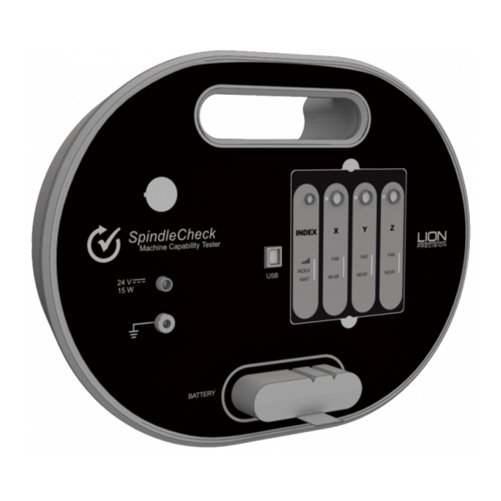
COMPONENT 1 - SPINDLECHECK DEVICE ELECTRONICS The sensor system electronics include driver electronics for the capacitive and index probes, an internal wireless router, a USB port for communicating with the PC, a battery slot, power and ground connections, a power switch, and probe position indicators useful during setup. -
Page 8: Index Sensor (Purple)
Index probe is over the steel. WAIT The wait indicator lights during the 60-90 second initialization period when power is first applied to the SpindleCheck device. No communication between the computer and device is possible during this time. Capacitive Displacement Sensors (X, Y, Z) The X, Y, and Z Axes each have a separate color-coded capacitive displacement sensor channel. -
Page 9: Component 2 - Capacitive Probes (X, Y, Z)
COMPONENT 2 - CAPACITIVE PROBES (X, Y, Z) Noncontact capacitive probes measure the distance to the precision target pin as it turns. The probes are 8 mm in diameter, have a total measurment range of 0.250 mm (0.01 inch), and a minimum gap (Near Gap) of 0.125 mm (0.005 inch). -
Page 10: Component 6 - Precision Target Pin
Index probe. The precision surfaces are important for accurate measurements. If these surfaces are damaged, the pin should be refinished by Lion Precision to restore an accurate reference surface. Part Numbers: 8mm pin – MFG5-1240 & 20mm pin – MFG5-1241. -
Page 11: Component 10 - Battery & Charger
Grounding the SpindleCheck device to the spindle housing may be necessary to reduce electrical noise from the machine’s environment. The ground strap includes a “banana” plug to connect to the SpindleCheck ground connector and a clamp to connect to a convenient point on the spindle housing. -
Page 12: Software Installation
Installation Procedure The SpindleCheck Inspector program is installed in the \Program Files (x86)\Lion Precision\Spindle Check Inspector directory on your hard disk. If you install the SpindleCheck Inspector software a second time using the same subdirectory, the previous installation will automatically be uninstalled first. -
Page 13: Software Basics
SpindleCheck device. If it is successful, the Home Screen will be displayed. If it does not find a connection to a SpindleCheck device, you will be given the option to Retry the connection, or to View Data previously collected. -
Page 14: Reading Measurement Screens
READING MEASUREMENT SCREENS Axis Names Some measurements read each axis separately (Warm-Up, Vibration, Repeatability, Thermal, Runout, Position Shift) and report results for the X, Y, and Z axes. Other measurements read the “radial” axis as a mathematical combination of X and Y (Total Error, Roundness, Roughness) and report results for the Radial and Axial axes. -
Page 15: Chart Area Time/Sample/Rpm
Pass/Fail If Pass/Fail numbers are entered into the Machine Manager > Pass/Fail, the Combined result will be compared to the Pass/Fail number. If no number has been entered in the Pass/Fail screen, a Pass/Fail test will not be performed. Best/Worst RPM For measurements taken across a range of spindle speeds, this area lists the best and worst performing speeds for each axis. -
Page 16: Preparing To Make Measurements
7. Install and position the measurement probes Power the SpindleCheck device Insert a battery into the SpindleCheck (or connect to power supply) and turn the power switch on. The NOT READY light will be on (Index channel) for about 90 seconds. During this time, no communication is possible with the device. -
Page 17: Launch Spindlecheck Inspector
When a machine has been loaded, the machine description will be listed in the top right corner next to the Lion Precision logo. If you are going to measure a machine, the first step is loading a machine in the Machine Manager. -
Page 18: Confirm Settings
The Target Pins are designed with a precise diameter and minimal roundness error. The SpindleCheck system must know the size of the Target Pin to make precise calculations during measurements. Be certain to select the correct pin size you are using during your measurement. - Page 19 Language Select your desired language and a message box will popup to confirm the action. After clicking “Yes” the program will shut down, and the user will need to restart the program, if clicking “No”, the language field changes back to previous language, no restart is necessary. Settings >...
-
Page 20: Settings > Wireless
Diagnostics The Diagnostics section lists data relative to the inner workings of the software and the electronics. These values may be needed by Lion Precision engineers to troubleshoot the system in the unlikely event that there is a problem. Settings > Wireless This Wireless Panel is for the user to change/update the wireless network name (SSID) and Wireless Password. -
Page 21: Select A Machine (Machine Manager)
Spindle Name: Identify the spindle to be measured • Spindle Type: Milling or Turning. Measurement values within SpindleCheck Inspector are calculated differently depending on the spindle type. If Company, Machine ID, Machine Type, Spindle Name, and Spindle Type are not NOTE loaded properly the new machine will not save. - Page 22 *.smmx file. This is the file which will be selected for import into another installation of SpindleCheck Inspector. To identify a single machine to export, select it in the list (highlighted text).
- Page 23 The data in the file is imported into the local database. Pass/Fail Each measurement available in SpindleCheck Inspector can have a Pass/Fail threshold. If no value or “0’ is entered, the Pass/Fail test will not be performed.
-
Page 24: Install The Target Pin
Install the Target Pin Target pins (8 mm diameter standard, 20 mm optional) are to be installed in the tool/part holder of the spindle to be measured. The etched line on the pin marks the depth of insertion into the collet. - Page 25 Z probe and the collar on the pin is approximately centered with the index probe. Go to Probe Setup function on SpindleCheck Inspector. Adjust X and Y axes as necessary to center the pin over the Z-axis probe.
- Page 26 Use the probe spacer and move the Z-axis probe to set the gap between the target pin and probe. After removing the spacer, the on-screen indicator should be near the center of the meter display (pointing in a vertical direction) and the Zaxis range lights on the SpindleCheck device should be green.
-
Page 27: Measurement Types
Final Positioning of index Probe Turn spindle so the Index Collar strip is away from the Index Probe. Use probe spacer to set Index Probe gap. Slowly rotate spindle once around to confirm Index signal is active then tighten Index Probe. Click Done on screen. -
Page 28: Warm-Up
POSITIONING CAPABILITY Warm-Up Related Standards: ISO 230-3, 6 ▪ ASME B5.54, B5.57, 7.6.2.1, 7.7.2.1 Process: 1. Start with a ‘cold’ spindle (minimum 12 hours of no operation before beginning test). 2. Select a duration (10-120 minutes) 3. Start the spindle turning at 75% of maximum. 4. -
Page 29: Vibration
At the conclusion of the test, the total range (maximum – minimum) for each axis is calculated and presented as Total Drift per Axis. The Combined Drift for the machine is the square root of the sum of squares of the individual Total Drift values. - Page 30 Description: The probes measure vibration in all three axes while spindle is not turning. According to international standards, the vibration value is “the maximum range of the displacement” during any 5 second period during the time of the test. Measurements are taken at over 1,000 samples/second (as required by standards). Every five seconds the maximum range (peak to valley) value is calculated for that 5 second interval for each axis and plotted on the chart.
-
Page 31: Repeatability
Repeatability Related Standards: ▪ ISO 230-2, ▪ ASME B5.54, 7.3; B5.57, 8.4 Process: 1. Test requires a non-rotating spindle 2. Set the number of samples (3-10; standards require 10) 3. Position the spindle and setup probes 4. Start test to take initial measurement. This position of the spindle will be the reference point for all other samples. -
Page 32: Thermal
Purpose: This test determines the machine’s ability to move the spindle (and/or table) and return to the initial position. As the mechanics of the machine wear, backlash and other issues will reduce the machine’s ability to accurately locate the cutting tool relative the workpiece. The measurement allows some prediction of the machine’s ability to hold tolerance for feature location. -
Page 33: Setup/Run
4. The first Target RPM indicator will display “Seeking” as it waits for the spindle to come to speed 5. When SpindleCheck measures a stable RPM within 5% of the Target the indicator will change to “Measuring” 6. The measurements are taken and the indicator changed to “Complete”... - Page 34 If the spindle speed setting on the machine produces an actual speed which is off by more than 5%, SpindleCheck will not take the measurement. Clicking the “Force” button will force SpindleCheck to take the measurement at the current speed.
-
Page 35: Total Error
Total Error Related Standards: ▪ ASME B89.3.4 ▪ Turning: ISO 230-7, 5.5; ASME B5.57, 7.5.3; ▪ Milling: ISO 230-7, 5.4; ASME B5.54, 7.5.3; ASME B5.57, 7.6.4 Description: Essentially, the Total Rotation Error is the measurement of the size of the envelope in which the axis rotates. -
Page 36: Runout
Runout Description: Runout is the Total Indicator Reading (TIR) of the surface of the target pin during rotation. As the pin turns, the maximum and minimum distance between the pin and the probe in each axis is recorded. The difference (Max-Min) is the Runout. Runout is measured in each axis. - Page 37 Related Standards: ▪ ASME B89.3.4, 2.7.11 Description: Position Shift measures the static location of the spindle at different spindle speeds. The total shift for each axis is the Maximum-Minimum of the values charted for that axis. The Combined Shift for the machine is the square root of the sum of squares of the individual Shift values: X²...
-
Page 38: Roundness
Roundness Related Standards: ▪ Turning: ISO 230-7, 5.5; ASME B5.57, 7.5.3 ▪ Milling: ISO 230-7, 5.4; ASME B5.54, 7.5.3; ASME B5.57, 7.6.4 Description: Roundness Capability describes the ability of the machine to create round features when drilling or boring with a milling type spindle, or any radial cutting on a lathe type spindle. The measurement of Roundness Capability is an accurate prediction of the roundness of features formed in this way. -
Page 39: Roughness
Roughness Related Standards: ▪ ASME: B89-3-4, A-7.3 ▪ Turning: ISO 230-7, 5.5; ASME B5.57, 7.5.3 ▪ Milling: ISO 230-7, 5.4; ASME B5.54, 7.5.3; ASME B5.57, 7.6.4 Description: Surface Roughness Capability is based on measurements of the “asynchronous” error motions of the spindle. -
Page 40: Measurement Sequences
MEASUREMENT SEQUENCES To make machine measurement faster and easier, two Measurement Sequences are available, Measure Machine Sequence and Crash Test Sequence. A sequence guides the user through a series of measurements from just one screen. The user simply clicks the Next button after each measurement. To skip a test, just click Next without performing the test. -
Page 41: Viewing Reports
VIEWING REPORTS Several reports are available in SpindleCheck Inspector. These reports make it easy to understand a machine’s capabilities, strengths, weaknesses, and general condition. Armed with this information, everyone can know the best and worst speeds for different operations, how the machine performs while warming up, if periodic maintenance is required and more. -
Page 42: Appendix A: Replacement Parts
Appendix A: Replacement Parts REPLACEMENT PART PRODUCT # CPD150 DRIVER & PROBE REPLACEMENT P017-7331 INCLUDES CALIBRATION PROBE SET P017-7485 INCLUDES 3 EA. C8-2.0-2.0 PROBES WITH 1 IEA. INDEX PROBE INDEXER PROBE FOR 8mm PROBE NEST P017-7070 INDEXER DRIVER P016-6701 AC ADAPTOR & POWER CORD MFG5-1230 BATTERY P017-7570... -
Page 43: Glossary
GLOSSARY Many of the definitions here are taken from ASME B89.3.4-2010: Axes of Rotation: Methods for Specifying and Testing. Asynchronous error motion - the portion of the total error motion that occurs at frequencies other than integer multiples of the rotation frequency. Asynchronous error motion comprises those components of error motion that are: (a) not periodic (b)periodic but occur at frequencies other than the spindle rotational frequency and its integer multiples, (c) periodic at frequencies that are subharmonics of the spindle rotational frequency. - Page 44 Least squares circle (LSC) center - the center of a circle which minimizes the sum of the squares of a sufficient number of equally spaced radial deviations measured from it to the error motion polar plot. Nonsensitive direction - is any direction perpendicular to the sensitive direction. Perfect spindle - a spindle having no motion of its axis of rotation relative to the reference coordinate axes.
- Page 45 Thermal drift - a changing distance or angle between two objects associated with a changing temperature distribution within the structural loop. Thermal drift plot - a time-based record of thermal drift. Thermal drift value - the difference between the maximum and minimum values over a specified period of time and under specified conditions.
-
Page 46: Approvals And Safety Considerations
APPROVALS AND SAFETY CONSIDERATIONS The SpindleCheck sensors and electronics are compliant with the following standards: • Safety: 61010-1 • EMC: 61326-1, 61326-2-3 To maintain compliance with these standards, the following operating conditions must be maintained: All I/O connecting cables must be shielded and less than three meters in length Use the included CE approved power supply. - Page 47 FCC RF Radiation Exposure Statement This equipment complies with FCC RF radiation exposure limits set forth for an uncontrolled environment. This device and its antenna must not be co-located or operating in conjunction with any other antenna or transmitter. “To comply with FCC RF exposure compliance requirements, this grant is applicable to only Mobile Configurations.
-
Page 48: Battery
• DO NOT ship recalled, damaged or non-conforming batteries back to Lion Precision. • For additional information on how to ship the SpindleCheck Inspector according to IATA’s regulation, please contact Lion Precision. Oakdale, MN, USA www.lionprecision.com 651-484-6544 www.lionprecision.com/two-year-warranty/ Document No. M017-7500.004... -
Page 49: Material Requirements
Mechanical Requirements Vibration The battery complies with UN T3 Transportation test [USDOT-E7052] and IEC62133:2012 Chapter 4.2.2 Shock The battery complies with: • UN T4 Transportation test [USDOT-E7052] • IEC62133:2012 Chapter 4.3.4 Drop The battery complies with IEC62133:2012 Chapter 4.3.3 Reliability Requirements Life Expectancy Given normal storage &... -
Page 50: Software License Agreement
If the terms of the agreement are not acceptable to you, return the product to LION PRECISION for full credit. The terms of the agreement are as follows: 1.
Need help?
Do you have a question about the SPINDLECHECK and is the answer not in the manual?
Questions and answers