
Subscribe to Our Youtube Channel
Related Manuals for Benning MA 4


Summary of Contents for Benning MA 4
- Page 1 BENNING MA 4 CEE measuring adapter (5-pin/3-pin) Operating manual Original English version 5116 de Version 1.04 10218133 08.09.2020...
-
Page 3: Table Of Contents
Table of contents Application ..................1 1.1. General functional description................1 Safety notes and precautions ............1 2.1. Basic information about safety ................1 2.2. Symbols used ....................1 Inspection characteristics of the measuring adapter ....... 2 Operating elements ................3 Connecting the measuring adapter .......... -
Page 4: Application
(high exposure to dust, moisture or excessive temperatures). BENNING ST 750 / ST 750 A / ST 755 / ST 760 Non-observance might involve damaging or destruction of the Devices of other manufacturers... -
Page 5: Inspection Characteristics Of The Measuring Adapter
BENNING MA 4 measuring adapter 3. Inspection characteristics of the measur- ing adapter All tests that can be carried out with your appliance tester for de- vices with shock-proof socket and that are supported by the measuring adapter can now be performed in an identical way for devices with CEE connector. -
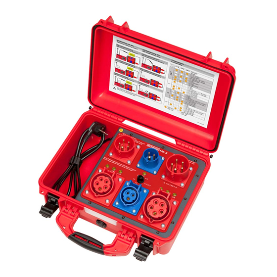
Page 6: Operating Elements
BENNING MA 4 measuring adapter 4. Operating elements... - Page 7 BENNING MA 4 measuring adapter Pos. Meaning PE socket for PE test probe (for R cable test) CEE connector: 16 A, 50 Hz to 60 Hz, 380 V to 415 V 3L+N+PE, 6h CEE connector: 16 A, 50 Hz to 60 Hz, 230 V...
-
Page 8: Connecting The Measuring Adapter
For appliance testing, the MA 4 must be connected to the For this test, no test sample may be connected! mains. Connect the ST 755 / 760 to the socket of the MA 4. Before carrying out the functional test and all tests... -
Page 9: Testing Of Three-Phase Devices With Functional Test
BENNING MA 4 measuring adapter 6.1.2. R 1 (LN-PE) 6.1. Testing of three-phase devices with func- Insu tional test Portable test sample Connect the CEE connector of the test sample to the CEE socket of the measuring adapter. For appliance testing with the differential cur- ... -
Page 10: Insu 2 (Sec.-Pe)
BENNING MA 4 measuring adapter 6.1.3. R 2 (sec.-PE) 6.1.4. R 3 (LN-sec.) Insu Insu Portable test sample Portable test sample Connect the CEE connector of the test sample to the Connect the CEE connector of the test sample to the CEE socket of the measuring adapter. -
Page 11: Insu 4 (Ln-Accessible Parts Without Pe)
BENNING MA 4 measuring adapter – Protective conductor current 6.1.5. R 4 (LN-accessible parts without PE) 6.1.6. I Insu Test procedure (VDE 0701 – 0702 / 0544-4) Portable test sample Portable test sample Connect the CEE connector of the test sample to the ... -
Page 12: Leak - Device Leakage Current
BENNING MA 4 measuring adapter – Contact current – Device leakage current 6.1.7. I 6.1.8. I Cont Leak Test procedure (VDE 0701 – 0702 / 0544-4) Test procedure (VDE 0751-1) Portable test sample Portable test sample Connect the CEE connector of the test sample to the Connect the CEE connector of the test sample to the CEE socket of the measuring adapter. -
Page 13: Pleak - Patient Leakage Current
BENNING MA 4 measuring adapter – Patient leakage current 6.1.10. Functional test 6.1.9. I PLeak Test procedure (VDE 0751-1) Portable test sample Portable test sample Connect the CEE connector of the test sample to the CEE socket of the measuring adapter. -
Page 14: Testing Of Three-Phase Devices With Alternative Leakage Current Method
BENNING MA 4 measuring adapter – Protective conductor resistance 6.2.1. R 6.2. Testing of three-phase devices with alterna- tive leakage current method Before testing The alternative leakage current measuring method must not be Before starting the test, determine the internal R resistance of the measuring adapter (see chapter 7). -
Page 15: Insu 1 - (Ln-Pe)
BENNING MA 4 measuring adapter 1 – (LN-PE) 2 – (sec.-PE) 6.2.2. R 6.2.3. R Insu Insu Portable test sample Before testing Disconnect the test sample from the mains supply. Switch the rotary switch (7) of the measuring adapter to position "L1-L2-L3". -
Page 16: (Ln-Accessible Parts Without Pe)
BENNING MA 4 measuring adapter 4 – (LN-accessible parts without PE) – Contact current (alt. leak.) 6.2.7. I 6.2.5. R Cont Insu Test procedure (VDE 0701-0702) Portable test sample Portable test sample Connect the CEE connector of the test sample to the CEE socket of the measuring adapter. -
Page 17: Device Leakage Current (Alt. Leak.)
BENNING MA 4 measuring adapter – Device leakage current (alt. leak.) – Patient leakage current (alt. leak.) 6.2.8. I 6.2.9. I Leak PLeak Test procedure (VDE 0751-1) Test procedure (VDE 0751-1) Portable test sample Portable test sample Connect the CEE connector of the test sample to the Connect the CEE connector of the test sample to the CEE socket of the measuring adapter. -
Page 18: Testing Of Extension Cables
– Protective conductor resistance 6.3.1. R Connect both cable connections to the corresponding For these tests, the MA 4 must be connected to the CEE sockets of the measuring adapter. mains using the CEE 32 connector. Connect the test probe of your appliance tester to the The ST 755 / 760 must be connected to the shock- PE socket (see pos. -
Page 19: Insu 1 - (Ln-Pe)
BENNING MA 4 measuring adapter 1 – (LN-PE) 6.3.4. Functional test and phase sequence test of 6.3.3. R Insu cables Before testing Before testing Switch the rotary switch (7) of the measuring adapter to position "L1-L2-L3". The functional test and phase sequence test of cables can be applied to CEE connecting cables and extension cables. - Page 20 BENNING MA 4 measuring adapter Circuit diagram...
-
Page 21: Function Table
PRCD 3-pin L1-N shorted Mobile power distributors (RCD) (types A, B) For these tests, the MA 4 must be connected to the L1 or N interrupted mains using the CEE 32 connector. L1-L2 shorted The ST 755 / 760 must be connected to the shock- proof socket of the measuring adapter. -
Page 22: Internal R Resistance Of The Measuring Adapter
BENNING MA 4 measuring adapter 7. Internal R resistance of the measuring Application adapter The PRCD / mobile power distributor (RCD) must be measuring adapter connected to the IEC socket of the ST 755 / 760. Start the R measurement on your appliance tester. -
Page 23: Technical Data
EN 61326-1 Figure Designation Item no. Measuring range 0.08 mA ... 10.0 mA AC Adapter cable for the MA 4 16 A / 400 V CEE connector – 4 % of the measured value 044163 Current accuracy ±40 μA 32 A / 400 V CEE coupling,... -
Page 24: Service Contacts
BENNING MA 4 measuring adapter 12. Service contacts Spare parts management Phone: +49 2871 93-553 E-mail: spareparts@benning.de General service requests Phone: +49 2871 93-556 E-mail: servicerequests@benning.de Returns management Phone: +49 2871 93-554 E-mail: returns@benning.de Training management Phone: +49 2871 93-557 E-mail: trainingscenter@benning.de... - Page 25 Support / helpdesk BENNING helpdesk team Phone: +49 2871 93-555 Fax: +49 2871 93-417 E-mail: @benning.de helpdesk Website: www.benning.de...
Need help?
Do you have a question about the MA 4 and is the answer not in the manual?
Questions and answers