
Related Manuals for Lenz Elektronik Digital plux BM3

Summary of Contents for Lenz Elektronik Digital plux BM3
- Page 1 BM3 Block Section Module BM3 Asymmetrical DCC Block and Signal Module Art. No. 22620 December 2005...
-
Page 2: Technical Data
BM3 Block Section Module The ABC modules BM1, BM2 and BM3 are designed to be used with ® Digital plus by Lenz or other standard digital control systems that have received an NMRA-conformance seal. If in doubt, ask the system supplier. Technical Data: The current-carrying capacities stated below may not be exceeded as this could damage the block section module! - Page 3 BM3 Block Section Module "Stop" signal indicates an asymmetry - the train will stop or slow down. Additional advantages of the ABC technology: • All locomotive functions (e.g. front lighting) can still be switched while the locomotive stops in front of the signal. •...
- Page 4 BM3 Block Section Module Using the BM3 block section module The BM3 block section module uses the ABC technology to facilitate the simply construction of a block section. Each block is equipped with a BM3 module so that an infinite number of blocks can be added.
- Page 5 BM3 Block Section Module The next train arrives from the previous block. When the rear-powered (pushed) train in the driving section reaches the braking section, the BM3 switches the driving and braking sections to asymmetrical digital voltage. As the pushing locomotive is already located in the driving section at that time, the GOLD decoder recognises this asymmetry and starts to brake.
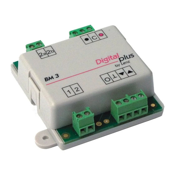
- Page 6 BM3 Block Section Module The above procedure requires that the first coach of the rear-powered (pushed) train is fitted with a power consumer, e.g. interior lighting. Installing and connecting the BM3 module The BM3 connections A brief overview of the BM3 connections: Figure 1 Driving section connection Stopping section connection...
- Page 7 BM3 Block Section Module Length of driving and braking sections First, define the length of the driving section (A). Keep in mind that the longest train on your layout must fit in this section! Then, define the length of the braking section (B) in front of the signal.
- Page 8 BM3 Block Section Module Block 1 Block 2 Braking Braking Driving section Driving section section section Direction of travel Figure 2 Connecting the driving and braking section Connect terminal (1) to the left continuous rail. Connect terminal (2) to the right rail before the braking section.
-
Page 9: Tips For Use
BM3 Block Section Module Connecting light signals Simply connect the BM3 signal outputs to the bulbs of the light signal. The voltage at these outputs is 15V DC. The maximum continuous current-carrying capacity of these outputs is 100mA. You can connect bulbs as well as luminous diodes to these outputs. - Page 10 BM3 Block Section Module Controlling the entry into a block section / exit signal Normally, the signal connected to a BM3 module automatically switches to "Clear" if the block that is next in the direction of travel is clear. It is possible that you do not want this to happen automatically because you want to define yourself when the train should accelerate again after a stop.
- Page 11 BM3 Block Section Module If you want to verify the occupancy status of braking and driving sections by means of the feedback function of the Digital plus system, simply connect the BM3 LR 101 to a LR101 feedback module: • Connect output (O) to one of the eight inputs of the LR101, •...
-
Page 12: North American Warranty
BM3 Block Section Module North American Warranty Lenz GmbH does everything it can do to ensure that its products are free from defects and will operate for the life of your model railroad equipment. From time to time even the best-engineered products fail either due to a faulty part or from accidental mistakes in installation.
Need help?
Do you have a question about the Digital plux BM3 and is the answer not in the manual?
Questions and answers