Table of Contents
Advertisement
Quick Links
Advertisement
Table of Contents

Related Manuals for Microsens Smart I/O Controller Digital

Summary of Contents for Microsens Smart I/O Controller Digital
- Page 1 Quick Start Guide Commissioning the Smart I/O Controller Digital V1.0.0...
-
Page 2: Table Of Contents
connecting the signal cables (digital inputs and outputs), and setting up access to the network management. For further information see the Web Manager of the managing MICROSENS switch or visit the MICROSENS website. MICROSENS GmbH & Co. KG, Kueferstr. 16, 59067 Hamm, Germany... -
Page 3: Mechanical Handling
and four mounting tabs for direct attachment to wall, ceiling or any other backing equipment. Top Hat Rail Mounting and Unmounting On its bottom side the Smart I/O Controller Digital housing (Figure 1, Pos. 1) is equipped with a clamp for mounting the device onto a standard top hat rail (Figure 1, Pos. 2). -
Page 4: Mounting Tabs
Commissioning the Smart I/O Controller Digital Mounting Tabs To attach the Smart I/O Controller Digital directly to a wall, ceiling or any other suitable backing equipment, use the four mounting brackets (Figure 3, Pos 1 to 4). Figure 3: Mounting tabs... -
Page 5: Connecting The Power Supply
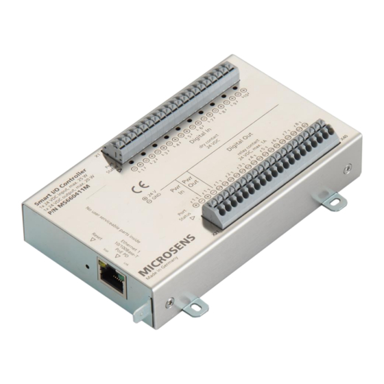
Smart I/O Controller Digital Connecting the Power Supply The MICROSENS Smart I/O Controller Digital can be supplied by two alternative power inputs (single or joint): PoE+ (PD) via Ethernet port (Figure 4, Pos. 1). External 24 VDC via push clamp ports X21 and X22 (Figure 4, Pos. 2) -
Page 6: Grounding With Poe Supply
(i.e. “earth”). Assuming, powering of the Smart I/O Controller Digital is done via a centralised far off PoE PSE device it is important to connect the grounding lead of the controller‟s chassis (Figure 4, Pos. 4) to the building‟s ground potential and thus to avoid “floating ground”... -
Page 7: Connecting The Digital Input/Output Ports
Smart I/O Controller Digital Connecting the Digital Input/Output Ports The Smart I/O Controller Digital is equipped with two 20-pin push clamp ports for digital input and output signals as well as input and output voltage (wire diameter 0.1 to 1.5 mm², stranded/solid). -
Page 8: Understanding The Status Leds
IPv6 has to be enabled. As soon as the Smart I/O Controller Digital is connected to the power supply (PoE or external supply) and to the corporate network the controller is accessible via a MICROSENS switch containing the MICROSENS SmartDirector. - Page 9 “Low” is processed as string value “0”. E.g., with a transformation setting “0=off, 1=on” the input port‟s value is translated into “off” or “on” before being processed by the Smart Director. MICROSENS GmbH & Co. KG, Kueferstr. 16, 59067 Hamm, Germany...
-
Page 10: Pairing The Smart I/O Controller Digital And The Microsens Switch
Pairing the Smart I/O Controller Digital and the MICROSENS Switch The following steps describe how to pair a Smart I/O Controller Digital via the Web Manager of a MICORSENS switch. Note: For this overview primarily the use of the Web Manager is shown. - Page 11 As long as no device of the suitable product type is created previously the column Pairing Actions of the respective Smart I/O Controller Digital is empty. A click on the button identify of the controller entry causes the port LEDs of this controller to blink several times. This ensures to use the correct controller for the next steps.
- Page 12 Select the fitting device from the drop-down list and click on the button pair as. The Smart I/O Controller Digital is now properly paired to the SmartDirector of the MICROSENS G6 Switch. Additionally the pairing process sets the previously empty device id to the correct value.
-
Page 13: Functional Test Of The Paired Smart I/O Controller Digital
After pairing the Smart I/O Controller Digital the Smart Director automatically generates the corresponding entries for the device and its enabled sensors and actors as well. The following steps describe how test the correct pairing of a Smart I/O Controller Digital via the Web Manager of the paired MICORSENS switch. Note: For this overview primarily the use of the Web Manager is shown. - Page 14 “1”. Depending on the prior attribute assignments the instance number can vary from the default numbering order. If any sensors are connected to the Smart I/O Controller Digital yet, both their last actual value and their last response are shown in the status list. Scroll to the right to see those status table entries.
-
Page 15: Updating The Device"S Firmware
Web Manager displays the received value. Updating the Device’s Firmware The Smart I/O Controller Digital has its own firmware that can be manually updated via the Web Manager of a connected MICROSENS G6 switch. To update the firmware prpceed as follows: Using the Web Manager: Start the web browser and enter the IP address of the respective G6 device. - Page 16 In the field update firmware enter the name of the firmware file you want to load into the controller and click on the button update firmware. Note: If the input field is left blank the latest firmware file is selected by default. MICROSENS GmbH & Co. KG, Kueferstr. 16, 59067 Hamm, Germany...
-
Page 17: Configuring Mqtt
The MICROSENS Smart I/O Controller Digital acts as MQTT client for sending and receiving MQTT messages from and to an MQTT broker in the network, regarding the controller‟s digital input and output port values. This is important if you want to use the Smart I/O Controller Digital in automation projects with interaction between field devices. - Page 18 Connection Status: Shows the connection status to the MQTT broker (read only). o Disconnected: No active connection to an MQTT browser in the network. o Accepted: The Smart I/O Controller Digital is connected to an MQTT broker. Client ID: The client ID that is defined on tab Device (read only).
-
Page 19: Using Mqtt Topics With Microsens Switches
It is not allowed using the MQTT mapping table and matching multiple topics to only one component is not appropriate (e.g. matching a sensor to a topic containing multiple rooms). MICROSENS GmbH & Co. KG, Kueferstr. 16, 59067 Hamm, Germany... - Page 20 (Device.factory.serial_number, e.g. “00345860”) {LOC}: SNMP SysLocation (Management.snmp.device_info.sys_location, e.g. “Office”) {NAM}: SNMP SysName (Management.snmp.device_info.sys_name, e.g. “MICROSENS G6 Micro Switch”) The variables can be combined e.g. in topics like “{SMO}/{MFG}_{MAC}/”. MICROSENS GmbH & Co. KG, Kueferstr. 16, 59067 Hamm, Germany...
-
Page 21: Disclaimer
All information in this document is provided „as is‟ and subject to change without notice. MICROSENS GmbH & Co. KG disclaims any liability for the correctness, completeness or quality of the information provided, fitness for a particular purpose or consecutive damage.
Need help?
Do you have a question about the Smart I/O Controller Digital and is the answer not in the manual?
Questions and answers