Advertisement
Quick Links
H28986
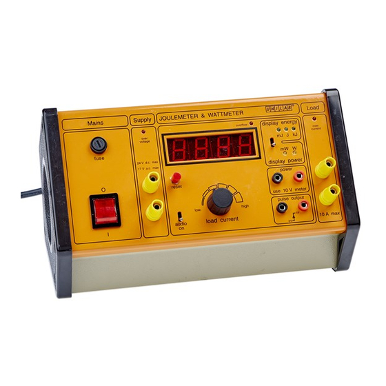
Joulemeter and Wattmeter
The Joulemeter and Wattmeter, is intended for measuring energy used (in joules and kilojoules)
and power (in watts) for a wide range of electrical and electronic devices, and is designed to
replace the previous model whilst improving the performance and being easier to use.
Technical Information
Check the operating voltage rating label on the instrument
Mains input
240V 50Hz,Instrument fuse T100mA
Input characteristics
Input range for linear operation
0 to ±24V peak, d.c. or a.c. (sine wave 0 to 17V RMS)
Frequency range
Input resistance without load 125kΩ
Output characteristics
Output resistance on lowest range = 1kΩ
Output resistance on highest range = 10mΩ plus wiring resistance
No load current with supply p.d. = 10V 10/1.25 x 105 A = 80µA
Maximum ratings on each range
The maximum thermal ratings of the shunts are represented by the following current maxima:
low
200µA
2mA
20mA
200mA
2A
high
10A
d.c. to 10kHz
NFU 381
Mains plug 5A recommended.
version H28986 2014
Advertisement

Summary of Contents for unilab NFU 381
- Page 1 H28986 Joulemeter and Wattmeter NFU 381 The Joulemeter and Wattmeter, is intended for measuring energy used (in joules and kilojoules) and power (in watts) for a wide range of electrical and electronic devices, and is designed to replace the previous model whilst improving the performance and being easier to use.
- Page 2 Accuracy 5% of F.S.D. typically 2% Dimensions Approx. overall 275mm wide, 165mm deep, 165mm high Weight 2.6 kg Warnings For your safety, this product should be used in accordance with these instructions, otherwise the protection provided may be impaired. This equipment is Class A according to the EMC standard EN 55011 and is intended for use in a non-domestic environment only.
- Page 3 Description The front panel of the instrument contains the following: • Input terminals - under Supply, yellow. • Output terminals - under Load, yellow. • Power sockets – marked ‘power’ - connect a 10V meter, red and black, observe the polarity.
- Page 4 The joulemeter/wattmeter measures the total power dissipation in the load, including that of any meters connected in the load circuit. The instrument records the product of the simultaneous values of current and potential difference (voltage across the load) at every instant. Moving iron meters record effective values of current and p.d.
- Page 5 Display operation When the instrument is reset, the display may be set to say '0.000', (depending on load current setting), if the reading goes above '9.999', the format "rolls over" to '10.00'. If the reading continues to above '99.99', the overflow LED lights and the reading becomes '00.00'. In general only one "rollover"...
- Page 6 Cool the cylinder to its original temperature and supply the same amount of heat electrically, using the heater measured via the joulemeter. Again record the temperature rise and compare the results. Further applications: Simple determinations can be made of the efficiency of electromechanical systems: An electric motor raising a known weight through a measured distance.
- Page 7 Potential Difference as Energy per Unit Charge Apparatus: Joulemeter/wattmeter Variable resistor/rheostat 0 to 10Ω, 1A rating Meters 1A d.c. and 5V d.c. Digital stopclock Source of smooth d.c. variable 0 to 6V d.c. e.g. 25V Variable OR Beaver Power Supply. Procedure: Adjust the supply voltage and the load resistance, R, to give a current, I, of 1A at a p.d.
- Page 8 An oscilloscope records the peak value of a p.d., Vo Further applications The circuits can be used to determine r.m.s. and half cycle average values of nonsinusoidal waveforms. For frequencies other than 50 - 60Hz, the frequency response of the voltmeter may be significant.
- Page 9 the power dissipated in the resistive component of the inductor is governed by the inductive reactance, which increases with frequency. Energy Stored by a Capacitor Apparatus: Joulemeter/wattmeter 10V d.c. meter instead of 1mA d.c. meter. Electrolytic capacitor, 1000uF 25V Resistor, 10kΩ...
- Page 10 Note: The inductor should be disconnected before the supply is switched off so that the circuit is isolated from the resulting back e.m.f. The meter is connected in the load circuit to avoid measurement of the current through the input resistance 125kΩ of the joulemeter. The d.c.
- Page 11 Philip Harris Education, 2 Gregory Street, Hyde, Cheshire, SK14 4RH Orders and Information Tel: 0845 120 4521 Fax: 0800 138 8881 Repairs Tel: 0845 120 3211 E-mail: techsupport@philipharris.co.uk Website: www.philipharris.co.uk © Philip Harris Education, 2002, 2014 version H28986 2014...
Need help?
Do you have a question about the NFU 381 and is the answer not in the manual?
Questions and answers