Advertisement
Quick Links
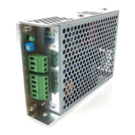
PS3L Series
Notes for Installation
1. PS3L switching power supplies can be
installed in either (A) or (B) directions as shown
below. For PS3L-E/F/G types, the operating
temperature vs. output current characteristics
vary with the mounting direction. See the der-
ating curves on page L-15.
( A )
2. Mount the switching power supply on a metal-
lic surface that provides adequate heat dissipa-
tion. Be sure to prevent heat built-up around
the power supplies.
3. Maintain 20 mm clearance between the power
supplies.
20 mm minimum
4. Use mounting screws of a proper length so that
screws do not penetrate into the housing of the
switching power supply 6 mm or more.
5. Mounting screws cannot be fastened on a PC
board. Be sure to fasten the screws on the
chassis side.
Adjustment of Output Voltage
L
The output voltage can be adjusted within ±10%
of the rated output voltage by using the V.ADJ
control on the front. Turning the V.ADJ clockwise
increases the output voltage. When using a
higher output voltage, reduce the output current
to make sure that the output capacity is within
the rating. Note that overvoltage protection may
work when increasing the output voltage.
• Do not use switching power supplies with electric equipment whose mal-
function or inadvertent operation may damage the human body or life
directly.
• Make sure that the input voltage and output current do not exceed the rat-
ings. If the input voltage and output current exceed the ratings, electric
shock, fire, or malfunction may occur.
• Do not disassemble, repair, or modify the power supplies, otherwise the
high voltage internal part may cause electric shock, fire, or malfunction.
• Do not touch the switching power supplies while input voltage is applied,
otherwise electric shock may occur.
www.idec.com
L-22
Overcurrent Protection
The output voltage drops automatically when an
overcurrent flows due to an overload or short cir-
cuit. Normal voltage is automatically restored
when the load returns to normal conditions.
Overvoltage Protection
(PS3L-A)
The PS3L-A uses a Zener diode for overvoltage
protection. In case overvoltage damages the
zener diode, contact IDEC for repair. Do not apply
an external overvoltage to the output terminal.
(PS3L-B/C/D/E/F/G)
( B )
The output is turned off by overvoltage protection
when an overvoltage is applied. When the output
voltage has dropped due to an overvoltage (120%
or more), turn the input off, and after one minute,
turn the input on again.
Series Operation
The following series operations are allowed.
(A)
(B)
AC
For the series operation (B), insert Schottky
diodes D as shown in the figure. Select a Schot-
tky diode in consideration of the rated current.
Power Supplies
Instructions
+
AC
IN
OUT
Load
-
+
Load
IN
OUT
-
+
IN
OUT
D
-
Load
+
IN
OUT
D
-
Safety Precautions
• Provide the final product with protection against malfunction or damage
that may be caused by the malfunction of switching power supplies.
• Operating temperatures should not exceed the ratings. Be sure to note the
derating characteristics. If the operating temperature exceeds the ratings,
electric shock, fire, or malfunction may occur.
• Blown fuses indicate that the internal circuits are damaged. Contact IDEC
for repair. Do not just replace the fuse and reoperate, otherwise electric
shock, fire, or malfunction may occur.
• Do not use the switching power supplies to charge rechargeable batteries.
USA: (800) 262-IDEC or (408) 747-0550, Canada: (888) 317-IDEC
Notes for Operation
1. Output interruption may indicate blown fuses.
Contact IDEC.
2. The internal fuse inside the power supply is for
AC input. When using with DC input, install an
external fuse for DC input.
To avoid blown fuses, select fuses in consider-
ation of the rated current of internal fuses.
Rated Current of Internal Fuses
Type No.
Rated Current of Fuse
PS3L-A
2A
PS3L-B
PS3L-C
3.15A
PS3L-D
2A
PS3L-E
4A
PS3L-F
PS3L-G
6.3A
3. Avoid overload and short-circuit for a long
period of time, otherwise the internal elements
may be damaged.
4. Not suitable for parallel operation.
5. DC input operation is not subject to safety
standards.
Insulation/Dielectric Test
When conducting an insulation/dielectric test,
short-circuit the input (between AC) and output
(between + and –). Do not apply or interrupt the
voltage suddenly, otherwise the surge voltage
may be generated and the power supply may be
damaged.
Advertisement

Related Manuals for IDEC PS3L Series


Summary of Contents for IDEC PS3L Series
- Page 1 fire, or malfunction may occur. shock, fire, or malfunction may occur. • Blown fuses indicate that the internal circuits are damaged. Contact IDEC • Do not disassemble, repair, or modify the power supplies, otherwise the for repair. Do not just replace the fuse and reoperate, otherwise electric high voltage internal part may cause electric shock, fire, or malfunction.
- Page 2 2-ø5 Holes 3-ø4 Holes A Side Mounting (screw from the back) 4-ø5 Holes 3-ø5 Holes 2-ø4 Holes 3-ø4 Holes 2-ø4 Holes B Side Mounting (screw from the back) (or 100) www.idec.com USA: (800) 262-IDEC or (408) 747-0550, Canada: (888) 317-IDEC L-21...