
Related Manuals for CAM GEAR Elite Series

Summary of Contents for CAM GEAR Elite Series
- Page 1 Elite-Series Fluid Heads Elite Series Fluid Head User Guide User Guide www.camgear.tv www.camgear-pro.com...
- Page 2 Copyright 2018 All rights reserved throughout the world. No part of this document may be stored in a retrieval system, transmitted, copied or reproduced in any way including, but not limited to, photocopy, photograph, magnetic or other record without the prior agreement and permission in writing of Camgear Inc. Disclaimer The information contained in this publication is believed to be correct at the time of printing.
-
Page 3: Table Of Contents
Content Safety Left View of Elite 8/10 Right View of Elite 8/10 Left View of Elite 12/15/18/20 Right View of Elite 12/15/18/20 Left View of Elite 25 Right View of Elite 25 Installation Illuminated Level Bubble Mounting and Levelling the Head Mounting and Dismounting the Camera Taking out and Placing back the Screw Key Mounting and Adjusting the Pan Bar... -
Page 4: Safety
Safety Important information on the safe installation and operation of these products. Read this information before operating the products. For your personal safety, read these instructions. Do not operate the product if you do not understand how to use it safely. Save these instructions for future reference. -
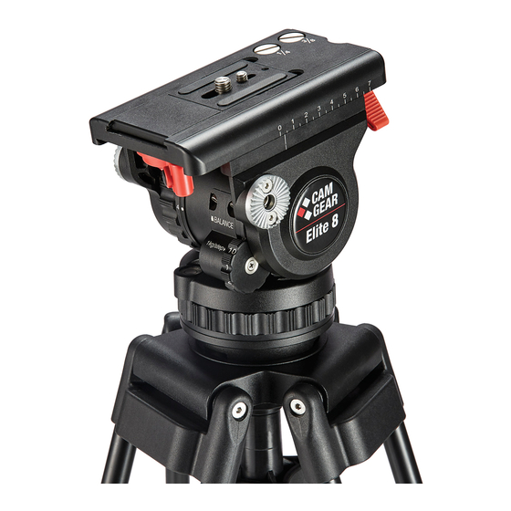
Page 5: Left View Of Elite 8/10
Left View of Elite 8/10 Tilt brake Quick release lock lever Quick release safety button Weight Counterbalance control Illuminated level bubble Battery compartment for level bubble Tilt drag control Rosette for left pan bar... -
Page 6: Right View Of Elite 8/10
Right View of Elite 8/10 Wedge plate Sliding plate Pan brake Weight Pan drag control Bowl clamp Screw key Sliding plate lock lever Rosette for right pan bar... -
Page 7: Left View Of Elite 12/15/18/20
Left View of Elite 12/15/18/20 Tilt brake Quick release lock lever Quick release safety button Weight Small-step counterbalance control Large-step counterbalance control Battery compartment for level bubble Illuminated level bubble Tilt drag control Rosette for left pan bar... -
Page 8: Right View Of Elite 12/15/18/20
Right View of Elite 12/15/18/20 Wedge plate Sliding plate Pan brake Weight Pan drag control Bowl clamp Screw key Sliding plate lock lever Rosette for right pan bar... -
Page 9: Left View Of Elite 25
Left View of Elite 25 Tilt brake Spindle of sliding plate Quick release lock lever Weight Quick release safety button Small-step counterbalance control Large-step counterbalance control Battery compartment for level bubble Illuminated level bubble Tilt drag control Rosette for left pan bar... -
Page 10: Right View Of Elite 25
Right View of Elite 25 Wedge plate Sliding plate Screw key Weight Pan brake Pan drag control Bowl clamp Sliding plate lock lever Tilt safety lock Release button for quick adjustment of sliding plate Rosette for right pan bar... -
Page 11: Installation
Installation (1/11) Illuminated Level Bubble All Elite fluid heads are fitted with an illuminating touch level bubble which allows easy levelling in poor lighting conditions. The illumination is activated by firmly tapping the bubble and will automatically switch off after approximately 60 seconds. Mounting and Levelling the Head 1. -
Page 12: Mounting And Dismounting The Camera
Installation (2/11) Mounting and Dismounting the Camera 1. Apply the pan and tilt brakes. NOTE: When using Elite 25 head, lock the head with the tilt safety lock when mounting or dismounting the camera. The blocking and clicking into position of the tilt safety lock is achieved by pulling out the red knob and turning it 90°. -
Page 13: Taking Out And Placing Back The Screw Key
Installation (3/11) 5. Attach the camera wedge plate to the camera around its centre of gravity. Additional screws are stored in the sliding plate. 6. Mount the camera wedge plate and camera onto the sliding plate. It will lock automatically and the lever will click audibly back into its initial position. -
Page 14: Mounting And Adjusting The Pan Bar
Installation (4/11) Mounting and Adjusting the Pan Bar Fit and adjust the pan bar to the desired position, tighten the clamp lever ensuring the teeth mesh fully. To adjust the position of the pan bar, loosen the clamp lever sufficiently to allow the rosettes to rotate without attaching the teeth of rosette. -
Page 15: Configuring The Normal Pan Bar
Installation (5/11) Configuring the Normal Pan Bar As standard, the pan bar is configured to mount on the right hand side of the fluid head. The pan bar can be configured for left hand mounting as follows: Configuring the Telescopic Pan Bar As standard, the telescopic pan bar is configured to mount on the right hand side of the fluid head. -
Page 16: Balancing The Payload
Installation (6/11) Balancing the Payload Before operating the fluid head, the payload (camera, lens and any other fitted accessories) must be correctly balanced to ensure safe and reliable operation. WARNING! When balancing the payload, it is important to be aware of the potential danger that an unbalanced payload will fall away suddenly. - Page 17 Installation (7/11) 2. Hold the pan bar firmly, disengage the tilt brake. Observe how the payload moves and where it stops. If the platform stops in a horizontal position (camera pointing directly forward) or falls away evenly in either direction, the balance is correct. (Figure 1) NOTE: When balancing camera on Elite 25 head, apply the pan brake and release the tilt brake and the tilt safety lock by pulling out the red knob and turning it 90°.
- Page 18 Installation (8/11) (C) If the payload tilts forwards, slide it towards the rear of the fluid head. Re-lock the sliding balance plate. (D) Re-check the movement of the payload. If further adjustment is required, repeat steps (A) to (C). NOTE: When using Elite 25, there are two ways to move the sliding plate, one is by pressing and holding the release button and rapidly move the sliding plate forward or backward (Figure 2).
-
Page 19: Adjusting The Counterbalance
Installation (9/11) Adjusting the Counterbalance The fluid head is equipped with payload range shifter (boost button) and multiple step counter- balance adjuster to accurately balance the payload. Note: Moving the counterbalance from one setting to another requires the head to pass the horizontal position to take effect. - Page 20 Installation (10/11) 4. If the payload continues to move upwards when released, the balance is set too high. Lower the balance adjuster setting by one increment and retest. 5. Tilt the payload through positive and negative angles of travel, checking that the payload remains at any angle of tilt unsupported.
-
Page 21: Adjusting The Drags
Installation (11/11) Adjusting the Drags The fluid head is equipped with multiple tilt and pan step drag controls. The drags help to eliminate jerks and vibrations when moving the fluid head during filming. The drags can also be fully disengaged. CAUTION! Always set the drag to the index positions. -
Page 22: Maintenance
Maintenance Transporting with the Attached Pan Bar To transport the fluid head with the pan bar attached, stow in the vertical position with the tripod legs to prevent damage. Cleaning Clean the fluid head regularly using a soft cloth. For heavier dirt use a soft brush and a mild detergent.