
Related Manuals for SPX MARLEY LLC

Summary of Contents for SPX MARLEY LLC
- Page 1 u s e r m a n u a l LLC water level control I N S TA L L AT I O N - O P E R AT I O N - M A I N T E N A N C E Z0628617_B ISSUED 07/2018 READ AND UNDERSTAND THIS MANUAL PRIOR TO OPERATING OR SERVICING THIS PRODUCT.
-
Page 2: Table Of Contents
contents This manual contains vital information for the proper installation Note and operation of the LLC controls. Carefully read the manual before installation or operation and follow all instructions. Save this manual for future reference. Quick Start Guide .......................4 Description ........................5 Operation ........................6 Water Makeup Function ....................7 HAND-OFF-AUTO Switch ..................7... - Page 3 However, since SPX Cooling Technologies does not control the tower location, or field installation, we cannot be responsible for addressing safety issues that are affected by these items.
-
Page 4: Quick Start Guide
quick start guide Connect incoming power here. Panel requires 120VAC 1 phase, 6 amp power with ground. If a makeup solenoid circuit is provided, connect the solenoid wires here at points 4A and 2A. This circuit provides 120 VAC power for the solenoid. Connect alarm and/or cutoff control wiring to the grey terminal points. -
Page 5: Description
description SYSTEM DIAGRAM Optional Field Components—by others LLC Components Junction Box by others if required Probe Pump System High and low alarm dry contacts 30'-0 Lead High and low cut-off dry contacts Control Panel Pump MU powered with 120V Display Solenoid Stilling Chamber... -
Page 6: Operation
operation Operation The LLC water level control system consists of special purpose liquid sensing relays on one or more individual circuit cards connected to a probe assembly located in the cold-water basin. Each circuit card contains one relay and external signaling is provided by each of these special purpose cards. -
Page 7: Water Makeup Function
operation A water level control system can be configured to meet various combination requirements. Since one individual circuit card is responsible for each func- tion, the size and circuitry varies in proportion to the number of operations desired. For example, a water level makeup control will require a control panel with one circuit relay card and three probes. -
Page 8: Internal Components
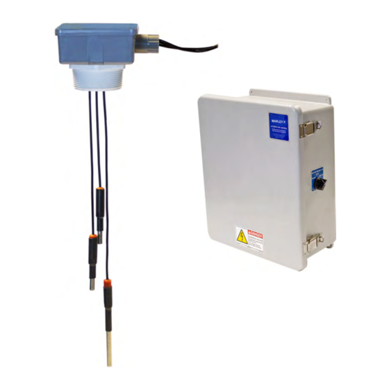
operation Inside view of an LLC Control Panel with Makeup, High Alarm, and Low Alarm. Internal Components of the LLC Control Panel LLC control panels are built to UL and CUL standards and are designed to provide the numerous configurations needed for cooling tower applications. All LLC control panels include a main circuit breaker with an additional circuit breaker and a HAND-OFF-AUTO switch provided when the system includes a water makeup circuit. -
Page 9: Electrode Probe Assembly
operation Stainless Steel Electrode Probe Assembly The electrode probe tips are stainless steel suspended from a noncorrosive PVC enclosure box with 30 feet of wire for each probe. A galvanized or stain- less steel stilling chamber is installed over the probes to calm the water for accurate readings. -
Page 10: Water Makeup Control Sequence
operation Water Makeup Control – Sequence of Operation – B Card Selector Switch in AUTO Position DE-ENERIZED ENERIZED ENERIZED CONTROL PANEL CONTROL PANEL CONTROL PANEL Power ON Power ON Power OFF Relay Relay Relay CIRCUIT CARD CIRCUIT CARD CIRCUIT CARD Valve Valve Valve... -
Page 11: High-Level Alarm Sequence
operation High Level Alarm – Sequence of Operation – B Card DE-ENERIZED ENERIZED ENERIZED CONTROL PANEL CONTROL PANEL CONTROL PANEL Power ON Power ON Power OFF Relay Relay Relay CIRCUIT CARD CIRCUIT CARD CIRCUIT CARD Contact Contact Contact with RELAY with RELAY with RELAY Open... -
Page 12: Low-Level Alarm Sequence
operation Low Level Alarm – Sequence of Operation – A Card DE-ENERIZED ENERIZED ENERIZED CONTROL PANEL CONTROL PANEL CONTROL PANEL Power ON Power ON Power OFF Relay Relay Relay CIRCUIT CARD CIRCUIT CARD CIRCUIT CARD Contact Contact Contact with RELAY with RELAY with RELAY Open... -
Page 13: Troupleshooting
troubleshooting The control panel has been tested before shipment and most issues lie outside of the control panel e.g. proper probe connections to the control panel and probe tip level heights in the basin of the cooling tower. In an effort to troubleshoot the system please check the following: •... -
Page 14: Electrode Probe Part Numbers
parts list Threaded Probe Tip Standard Part Number 2580240 Includes red cap and small hat-shaped copper crimp-on connector Probe, Reference/GND “Tip Only” Part Number D20718 Electrode Probe Assembly Additional part numbers can be found on the next page... -
Page 15: Relay Circuit Card Part Numbers
parts list Relay Circuit Card Part Number D55194 – Used for Makeup, High Alarm and High Cutoff (LLC24B2F50N) Part Number D55195 – Used for Low Alarm and Low Cutoff (LLC24A2F50N) Part Number Description 2038884 H-O-A Switch D55194 Makeup Relay Card D55194 High Alarm Relay Card D55194... -
Page 16: Wiring Diagrams
wiring diagrams – contents Drawing Number Description Page 08-24248 Makeup High Alarm High Cutoff Low Alarm Low Cutoff 08-24233 Makeup High Alarm Low Alarm 08-24218 Makeup 08-24219 High Alarm 08-24220 Low Alarm 08-24221 High Cutoff 08-24222 Low Cutoff 08-24230 High Cutoff Low Alarm 08-24231 Low Cutoff... - Page 48 SPX COOLING TECHNOLOGIES, INC. 7401 WEST 129 STREET Z0628617_B ISSUED 07/2018 OVERLAND PARK, KS 66213 USA © 2009-2018 SPX COOLING TECHNOLOGIES ALL RIGHTS RESERVED 913 664 7400 | spxcooling@spx.com In the interest of technological progress, all products are subject to design spxcooling.com...
Need help?
Do you have a question about the MARLEY LLC and is the answer not in the manual?
Questions and answers