Table of Contents
Advertisement
Advertisement
Table of Contents

Summary of Contents for Art Voice Channel
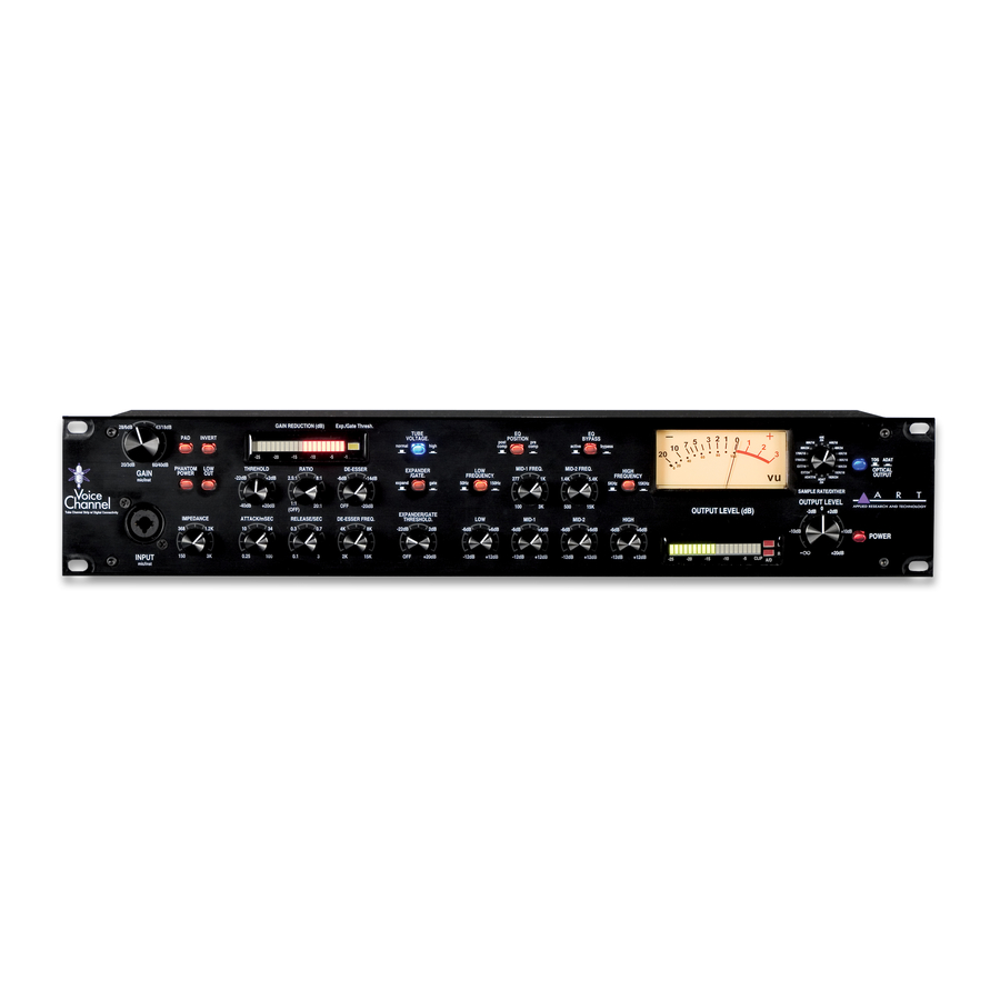
- Page 1 Voice Channel™ Tube Channel Strip with Digital Connectivity USER’S GUIDE...
-
Page 2: Important Safety Instructions - Read First
IMPORTANT SAFETY INSTRUCTIONS – READ FIRST This symbol, wherever it appears, This symbol, wherever it appears, alerts alerts you to the presence of uninsulated you to important operating and maintenance dangerous voltage inside the enclosure. Voltage instructions in the accompanying literature. that may be sufficient to constitute a risk of shock. -
Page 3: Table Of Contents
S/PDIF Output Jack... 13 AES/EBU Output Jack... 13 USB Jack... 13 APPLICATIONS ... 14 Bypassing Components Of The Voice Channel™... 14 Optimizing The Preamp For Lowest Noise ... 14 Utilizing Pre/Post Compression EQ... 14 WARRANTY INFORMATION... 15 SERVICE ... 16 SPECIFICATIONS... - Page 4 LIST OF FIGURES FIGURE 1 – Preamp section ... 6 FIGURE 2 – Dynamics Section... 6 FIGURE 3 – Equalizer Section ... 9 FIGURE 4 – Signal Flow Block Diagram ... 10 FIGURE 5 – Output Section ... 11 FIGURE 6 – Rear Panel ... 11 FIGURE 7 –...
-
Page 5: Introduction
AC Power Hookup The ART Voice Channel has an internal power supply. Only connect the unit to mains power of the type marked on the rear panel. The power source must provide a good ground connection, and the ground pin on the mains plug should never be defeated. -
Page 6: Front Panel Controls And Jacks
Impedance Control This knob sets the load impedance at the front and rear panel XLR inputs of the Voice Channel™. Use the IMPEDANCE CONTROL to subtly tune the sound of your microphone. Various microphones will change their sound at differing load impedances. The correct setting is subjective. Adjust this control to personal taste. -
Page 7: Tube Voltage Switch
Tube Voltage Switch The vacuum tube preamp section can be adjusted to run at two different plate voltages. Refer to Figure 2 for the location of the switch. Choose the “NORMAL” setting for adding warmth to the input signal. This setting has an increased amount of tube saturation at higher signal levels. -
Page 8: Dynamic Processor Controls
The De-esser is frequency tunable. Threshold Control This control sets the level, above which the Compressor/Limiter in the Voice Channel™ starts to act on the input signal. As the control is turned clockwise, more input signal is required to begin reducing gain. The compression action can be seen in the Gain Reduction LED meter. -
Page 9: Release Control
Release Control The RELEASE control sets the time the Compressor/Limiter takes to increase the gain after the input level drops. Longer settings maintain the dynamics of the input signal, while shorter settings reduce the dynamics. Shorter settings will also increase the apparent reverberation, and at extreme gain reduction settings, lead to “breathing”... -
Page 10: Semi-Parametric Eq
Semi-Parametric EQ The ART Voice Channel™ offers a four-band semi-parametric equalizer. The EQ can be bypassed as well as positioned before or after the dynamics processing section. Each band has + 15dB of control range. The High and Low EQ bands are shelving type with a switch selectable turnover point. -
Page 11: Output Level Control
This control affects the levels sent to the A/D converter and to the balanced analog OUTPUT jacks. Output Level Meters The ART Voice Channel™ provides both analog and digital output meters. The meters monitor the signal level just after the output control. This signal is sent to both the analog and digital outputs. -
Page 12: Sample Rate/Dither Control
If the A/D insertion jacks are not being used, both channels 1 and 2 carry the same signal. If the ADAT INPUT is also being used, channels 3 thru 8 are passed through along with channels 1 and 2 of the ART Voice Channel™. -
Page 13: Rear Panel Connections
EQ and dynamics processing of the Voice Channel™. Balanced Output The analog output of the Voice Channel™ is available on both a 1/4” TRS balanced jack and an XLR jack. This output is active balanced, and will adjust to balanced or unbalanced termination without gain change. The LED and analog meter monitor the level present at this output. -
Page 14: Adat Input Jack
The optical ADAT input allows the Voice Channel™ A/D converter to synchronize to systems using ADAT optical connections. The Voice Channel™ inserts its output in channels 1 and 2 of the ADAT stream while passing through channels 3 thru 8. Select ADAT/16 or ADAT/24 with the Sample Rate control on the front panel to enable this mode. -
Page 15: Applications
Optimizing The Preamp For Lowest Noise The preamp of the ART Voice Channel™ can be optimized for low noise by combining use of the PAD and Input GAIN control for mic and line level signals. NOTE: The PAD control has no effect on the INSTRUMENT INPUT (Front panel 1/4”... -
Page 16: Warranty Information
WARRANTY INFORMATION Limited Warranty: Applied Research and Technology will provide warranty and service for this unit in accordance with the following warrants: Applied Research and Technology, (A R T) warrants to the original purchaser that this product and the components thereof will be free from defects in workmanship and materials for a period of three years from the date of purchase. -
Page 17: Service
SERVICE The following information is provided in the unlikely event that your unit requires service. 1) Be sure that the unit is the cause of the problem. Check to make sure the unit has the proper power supplied, all cables are connected correctly, and the cables themselves are in working condition. -
Page 18: Specifications
Note: 0 dBu = 0.775 VRMS, 0 dBV = 1 VRMS ART maintains a policy of constant product improvement. ART reserves the right to make changes in design, or make additions to, or improvements upon, this product without any obligation to install same on products previously manufactured. Therefore, specifications are subject to change without notice. - Page 19 NOTES...
- Page 20 www.artproaudio.com E-mail: support@artproaudio.com © 2006 Applied Research & Technology 165-5004-103...
Need help?
Do you have a question about the Voice Channel and is the answer not in the manual?
Questions and answers