Advertisement
Quick Links
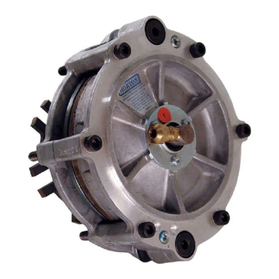
HT650
Fan Drive
TM
Service Instructions
When unpacking your product, remove all components and inspect them to
ensure that no damage occurred during shipping. If any components are missing
or damaged, contact Horton, Inc. at 1-800-621-1320 immediately. Do not return
the product to the retailer or point of purchase.
Advertisement

Related Manuals for Horton HT650

Summary of Contents for Horton HT650
- Page 1 When unpacking your product, remove all components and inspect them to ensure that no damage occurred during shipping. If any components are missing or damaged, contact Horton, Inc. at 1-800-621-1320 immediately. Do not return the product to the retailer or point of purchase.
-
Page 2: Table Of Contents
Fan Drives. Following the instructions carefully will provide the safest and most trouble-free operation. Horton uses the following special notices to give warning of possible safety related problems which could cause serious injury and provide information to help prevent damage to equipment. -
Page 3: Pre-Installation
NOTE Parts replacement and/or repair of your Horton DIESLTEMP® Fan Drive should be performed only by the Horton Factory or an authorized Horton Distributor or Dealer to keep your warranty coverage intact during the warranty period... -
Page 4: Every 25,000 Miles
Every 25,000 Miles Fan and Fan Belt 1. Check the fan for looseness and damage, such as bent, cracked or missing blades, loose rivets or missing weights. Retighten if loose. Replace if damaged. 2. Check for adequate clearance between the fan and the fan shroud or other engine compartment components. -
Page 5: Repair Kit Installation
REPAIR KIT INSTALLATION R e m o v e t h e s i x S o c k e t H e a d C a p S c r e w s ; t h e n , r e m o v e a n d d i s c a r d t h e t w o S h o u l d e r S c r e w s . - Page 6 Lubricate the new O-ring Seal and O-ring seal contact surfaces of the Air Chamber with the o-ring lubricant supplied in the Repair Kit; then, install the new O-ring Seal into the Air Chamber. Press the new Piston into the Air Chamber. NOTE If you are installing a new Drive Sleeve, continue with Step 9. If you are not installing a new Drive Sleeve go to Step 15. Chamber Piston O-ring Seal Steps 4-8 Remove the Hex. Head Cap Screw and Washer; then, slide the Mounting Bracket and Hex. Bracket off the splined hub of the Friction Disc.
- Page 7 13. Install the two new Silicone Sleeves over the new Compression Springs and onto the Drive Sleeve. 14. Place the two new Seal Washers on top of the new Compression Springs. Seal Washer Drive Sleeve Air Chamber Piston Silicone Sleeve Compression Steps 13-14 Spring...
-
Page 8: Installation
20. Remove the three Pan Head Screws and the old Retaining Washer; then, remove the old Rotary Air Union and old O-ring Seal. 21. Lubricate the new O-ring Seal with the o-ring lubricant supplied in the Repair Kit; then, install the new O-ring Seal into the Air Chamber. 22. Press the new Rotary Air Union into the Air Chamber and new O-ring Seal. 23. Slide the new Retaining Washer over the new Rotary Air Union. 24. Install and tighten the three Pan Head Screws to 13-17 In. Lbs. [1.5-1.9 N•m] torque. - Page 9 Make the air line connections between the Solenoid Valve and the Fan Drive. Check for proper air pressure to the Fan Drive. This measurement should always be taken at the Fan Drive air inlet port. NOTE To assure maximum horsepower carrying capacity of the Fan Drive and to prevent damage to the Fan Drive, there must be a minimum pressure of 90 to 120 psi [6.2 to 8.3 bar] to the Fan Drive upon engagement.
-
Page 10: Troubleshooting
TROUBLESHOOTING SOLUTION PROBLEM PROBABLE CAUSE Fan Drive Electrical Problem fails to Check electrical Broken circuit (Normally engage connections. Open System). Check wiring according Improperly wired. to diagram. Thermal Switch incorrect for Check Thermal Switch application. (N.O. or N.C.). Bad Solenoid Valve. Replace the Solenoid Valve. - Page 11 PROBLEM PROBABLE CAUSE SOLUTION Fan Drive Electrical Problem cycles Check electrical frequently Poor ground wire connections. connection. Check temperature Improper temperature setting of all controls. control settings. T h e r m a l S w i t c h setting should engage the Fan Drive 10 higher than the full...
- Page 12 Our culture of innovation delivers high-performance ® products that last and services that help you meet your commitments. Trust Horton to help your products last longer, run quieter and consume less fuel.
Need help?
Do you have a question about the HT650 and is the answer not in the manual?
Questions and answers
what are the set screws for on a horton 650 fan clutch and do they need to be installed