Table of Contents

Subscribe to Our Youtube Channel
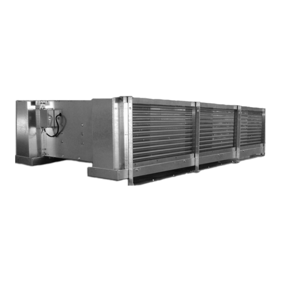
Related Manuals for SPX SGS REFRIGERATION STC Series


Summary of Contents for SPX SGS REFRIGERATION STC Series
- Page 1 u s e r m a n u a l REFRIGERATION STC Series twin unit cooler I N STA L L AT I O N - O P E R AT I O N - M A I N T E N A N C E E329630 ISSUED 02/2020 READ AND UNDERSTAND THIS MANUAL PRIOR TO OPERATING OR SERVICING THIS PRODUCT.
-
Page 2: Table Of Contents
contents 1 Receipt Of Equipment ..............................3 Inspection ................................3 Loss of Gas Holding Charge ........................3 2 Assembly of Components ............................3 Shipped Loose Parts ............................3 Dielectric Flange Union ..........................3 Refrigerant Distributor Nozzle ........................ 3 Expansion Valve (optional item) ......................3 3 Rigging Instructions ................................ -
Page 3: Receipt Of Equipment
receiving and installation 1 RECEIPT OF EQUIPMENT position. Do not position the bulb on the top or the bottom of the pipe. Clamp the bulb down flush and tight against the pipe and insulate. Never locate the bulb on a trap or downstream from a trap. 1.1 INSPECTION Expansion valves are NOT adjusted at the factory prior to shipment. - Page 4 receiving and installation unit using less than all hanger or shipping leg holes. The shipping place before the unit is hung. See Sections 2.3 and 2.4. support legs can be removed after the unit is hung. See unit drawing The unit must be level in all directions to insure proper drainage for mounting hole locations.
- Page 5 installation Table 1 — Unit Dimensions Model Dimensions in Heater Removal Clearance in Fan Quantity Fan Diameter Rows Length Width Height Header End Return End 55.00 56.00 24.00 34.00 51.75 24" 55.00 64.00 24.00 34.00 59.75 55.00 70.00 24.00 34.00 65.75 61.00 62.00...
-
Page 6: Refrigerant Warning
installation 5 REFRIGERANT WARNING of ¼” drop per running foot. The drain line should be the same size, or one size larger then drain pan connections. A drain line The use of any refrigerant can be dangerous under certain trap should be installed to prevent warm moist air from migrating conditions. -
Page 7: Refrigeration Piping
installation 6.2 REFRIGERATION PIPING IMPORTANT—The STC units have not been designed to carry the weight of any external piping or valves. Improper support Installation design must conform to all local and national codes, of external piping and valves may result in unit breakage and laws and regulations applying to the site of installation. -
Page 8: Hot Gas Interpiping
installation Coil System Flange fiber gasket Hex head bolt with isolation sleeve Hex nut SAE flat washer SAE flat washer Steel socket-weld Fiber isolation male flange washer Aluminum female flange FIGURE 4 Aluminum Flange Assembly 6.3 HOT GAS INTERPIPING 6.5 DXA AND SUCTION ACCUMULATORS If the unit was ordered with hot gas defrost the drawing shipped Do not use units with Direct Expansion Ammonia (DXA) feed below with the unit will contain the piping connection locations for the... -
Page 9: Electrical
installation 7 ELECTRICAL Wiring for a unit with Air or Hot Gas Defrost requires power to the fan motors terminal block only. The fan motor terminal block is FOR SAFETY BEFORE SERVICING: located on the end panel at the unit end opposite the refrigerant If the STC Series unit is equipped with an electrical power disconnect connection end of the unit. - Page 10 installation FAN MOTORS FAN MOTORS TERMINAL BLOCK TERMINAL BLOCK INSIDE UNIT INSIDE UNIT 3 PHASE SINGLE PHASE FAN MOTOR FAN MOTOR CIRCUIT CIRCUIT FIGURE 6 Air Defrost Wiring 230/380/460/575/3/60...
- Page 11 installation FIGURE 7 Electric Defrost Wiring 230/3/60...
- Page 12 installation FIGURE 8 Electric Defrost Wiring 380/460/575/3/60...
- Page 13 installation Table 3 — 24" Fan EDL Heater Data EDL Heater Full Load Amps Model Fan Quantity 230V 380V 460V 575V Total kW Circuit 1 Circuit 2 Circuit 3 Circuit 4 Circuit 1 (3) Circuit 2 (4) Circuit 1 Circuit 2 Circuit 1 Circuit 2 STC1*-43-A, STC1*-44-A 5.50 14.12...
- Page 14 installation Table 4 — 30" Fan EDL Heater Data EDL Heater Full Load Amps Model 230V 380V 460V 575V Quantity Total kW Circuit 1 Circuit 2 Circuit 3 Circuit 4 Circuit 1 (3) Circuit 2 (4) Circuit 1 Circuit 2 Circuit 1 Circuit 2 STC1*-43-C, STC1*-44-C 6.50...
- Page 15 installation Table 5 — 24" Fan ED Heater Data ED Heater Full Load Amps Model Fan Quantity 230V 380V 460V 575V Total kW Circuit 1 Circuit 2 Circuit 3 Circuit 4 Circuit 1 Circuit 2 Circuit 1 Circuit 2 Circuit 1 Circuit 2 STC1*-43-A, STC1*-44-A 4.00...
- Page 16 installation Table 6 — 30" Fan ED Heater Data ED Heater Full Load Amps Model 230V 380V 460V 575V Quantity Total kW Circuit 1 Circuit 2 Circuit 3 Circuit 4 Circuit 1 (3) Circuit 2 (4) Circuit 1 Circuit 2 Circuit 1 Circuit 2 STC1*-43-C, STC1*-44-C 4.80...
-
Page 17: Suggested No Defrost Requirement Sequence Of Operation
installation 7.3 SUGGESTED NO DEFROST REQUIREMENT The defrost timer energizes the liquid line solenoid valve SEQUENCE OF OPERATION allowing refrigerant to flow into the unit, cooling the coil and refreezing any remaining condensate drops that are still Used for units with a suction temperature above freezing. present. -
Page 18: Operation
operation 8.0 OPERATION 8.1 PRE-START UP After the installation is completed, a review of the following items For DIRECT EXPANSION systems let the system balance out should be preformed before the system is placed into operation: at the desired room temperature and check the operation of the expansion valve by properly measuring the superheat at the Check electrical connections, fan bushing set screws, motor sensing bulb. -
Page 19: Maintenance
maintenance 9 MAINTENANCE all electrical power to the unit has been turned off before any work is performed. Remove the fan guard as described in Section 9.3. Loosen two bolts from the bushing that hold the fan onto the A preventive maintenance schedule should be established as soon motor shaft. -
Page 20: Replacement Parts List
maintenance 10 REPLACEMENT PARTS LIST Following are major replacement parts of standard STC Series units. Model Number, Serial Number, and voltage will be necessary to identify the correct replacement part. Table 7—Motor and Fan Air Flow Up (U) Hub on Air 230/460/3/60 575/3/60 Air Flow Down (D) Hub on Air... -
Page 21: Maintenance Data
maintenance 11 MAINTENANCE DATA Drain Pan Cabinet and Coil Motor Electric Heater Water Defrost Date Performed Inspection and Inspection and Inspection Inspection Inspection Pan Inspection Cleaning Cleaning... - Page 24 7401 WEST 129 STREET E329630 ISSUED 02/2020 OVERLAND PARK, KS 66213 USA © 2020 SPX COOLING TECHNOLOGIES, INC ALL RIGHTS RESERVED 913 664 7400 | spxcooling@spx.com In the interest of technological progress, all products are subject to design and/or spxcooling.com...
Need help?
Do you have a question about the SGS REFRIGERATION STC Series and is the answer not in the manual?
Questions and answers