Table of Contents
Advertisement
Thank you for purchasing the MSI
PRO/ H410M PRO-VH
information about board layout, component overview, BIOS
setup and software installation.
Contents
Safety Information ........................................................................................... 2
Specifications ................................................................................................... 3
Rear I/O Panel ................................................................................................. 7
LAN Port LED Status Table ........................................................................................7
Overview of Components ................................................................................ 8
CPU Socket .................................................................................................................9
DIMM Slots................................................................................................................10
M2_1~2: M.2 Slots ...................................................................................................10
PCI_E1~2: PCIe Expansion Slots ..............................................................................11
SATA1~4: SATA 6Gb/s Connectors ...........................................................................11
JFP1, JFP2: Front Panel Connectors .......................................................................12
JAUD1: Front Audio Connector ................................................................................12
ATX_PWR1, CPU_PWR1: Power Connectors ...........................................................13
JUSB1: USB 2.0 Connector ......................................................................................14
JUSB2: USB 3.2 Gen 1 5Gbps Connector .................................................................14
CPU_FAN1, SYS_FAN1: Fan Connectors .................................................................15
JTPM1: TPM Module Connector ...............................................................................15
JCI1: Chassis Intrusion Connector ...........................................................................16
JCOM1: Serial Port Connector .................................................................................16
JBAT1: Clear CMOS (Reset BIOS) Jumper ...............................................................17
EZ Debug LED ...........................................................................................................17
JRGB1: RGB LED connector (H410M PRO) ..............................................................18
JRAINBOW1: Addressable RGB LED connector (H410M PRO) ...............................18
UEFI BIOS ....................................................................................................... 19
BIOS Setup ................................................................................................................20
Entering BIOS Setup .................................................................................................20
Resetting BIOS ..........................................................................................................20
Updating BIOS...........................................................................................................21
Installing OS, Drivers & Utilities ................................................................... 22
Installing Drivers ......................................................................................................22
Installing Utilities .....................................................................................................22
motherboard. This User Guide gives
10..............................................................................................22
®
H410M PRO/ H410M-A
®
1
Contents
Advertisement
Table of Contents

Related Manuals for MSI H410M PRO


Summary of Contents for MSI H410M PRO
-
Page 1: Table Of Contents
JCOM1: Serial Port Connector .................16 JBAT1: Clear CMOS (Reset BIOS) Jumper ...............17 EZ Debug LED ......................17 JRGB1: RGB LED connector (H410M PRO) ..............18 JRAINBOW1: Addressable RGB LED connector (H410M PRO) .......18 UEFI BIOS ....................... 19 BIOS Setup ........................20 Entering BIOS Setup ....................20 Resetting BIOS ......................20... -
Page 2: Safety Information
Safety Information ∙ The components included in this package are prone to damage from electrostatic discharge (ESD). Please adhere to the following instructions to ensure successful computer assembly. ∙ Ensure that all components are securely connected. Loose connections may cause the computer to not recognize a component or fail to start. -
Page 3: Specifications
1x M.2 slot with E key for WiFi module only ∙ 1x VGA port, supports a maximum resolution of 2048x1536 ∙ @50Hz, 2048x1280 @60Hz, 1920x1200 @60Hz (H410M PRO & H410M PRO-VH) Onboard ∙ 1x DVI-D port, supports a maximum resolution of 1920x1200 Graphics @60Hz (H410M PRO &... - Page 4 1x TPM module connector ∙ 1x Chassis Intrusion connector ∙ 1x Clear CMOS jumper ∙ 1x 4-pin RGB LED connector (H410M PRO) ∙ 1x 3-pin RAINBOW LED connector (H410M PRO) ∙ 4x EZ Debug LED Continued on next page Specifications...
- Page 5 Continued from previous page ∙ 1x VGA port (H410M PRO & H410M PRO-VH) ∙ 1x DVI-D port (H410M PRO & H410M-A PRO) ∙ 1x HDMI port ∙ 2x USB 3.2 Gen1 5Gbps Type-A ports Back Panel Connectors ∙ 1x PS/2 keyboard/ mouse combo port ∙...
- Page 6 Continued from previous page ∙ LAN Manager ∙ Mystic Light (H410M PRO) ∙ User Scenario ∙ Hardware Monitor ∙ True Color Dragon Center Features ∙ Live Update Please refer to http:// ∙ DPC Latency Tuner download.msi.com/manual/ mb/DRAGONCENTER2.pdf for ∙ Speed Up more details.
-
Page 7: Rear I/O Panel
Rear I/O Panel Line-out (H410M PRO & PS/2 Mouse/ Line-in H410M PRO-VH) Keyboard USB 3.2 Gen 1 5Gbps Type-A USB 2.0 Type-A DVI-D Mic-in (H410M PRO & H410M-A PRO) LAN Port LED Status Table Link/ Activity LED Speed LED Status... -
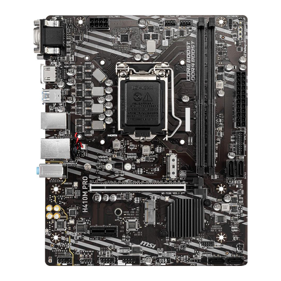
Page 8: Overview Of Components
Overview of Components CPU Socket CPU_FAN1 CPU_PWR1 SYS_FAN1 DIMMA1 DIMMB1 JARINBOW1 (H410M PRO) 50.89mm* ATX_PWR1 JBAT1 JUSB2 SATA3 PCI_E1 SATA4 M2_2 M2_1 PCI_E2 JTPM1 SATA2 JAUD1 SATA1 JFP2 JRGB1 JCI1 (H410M PRO) JUSB1 JFP1 JCOM1 * Distance from the center of the CPU to the nearest DIMM slot. -
Page 9: Cpu Socket
Always unplug the power cord from the power outlet before installing or removing ∙ the CPU. ∙ Please retain the CPU protective cap after installing the processor. MSI will deal with Return Merchandise Authorization (RMA) requests if only the motherboard comes with the protective cap on the CPU socket. ∙... -
Page 10: Dimm Slots
The stability and compatibility of installed memory module depend on installed ∙ CPU and devices when overclocking. ∙ Please refer www.msi.com for more information on compatible memory. M2_1~2: M.2 Slots Please install the M.2 device into the M.2 slot as shown below. Supplied 30º... -
Page 11: Pci_E1~2: Pcie Expansion Slots
∙ If you install a large and heavy graphics card, you need to use a tool such as MSI Gaming Series Graphics Card Bolster to support its weight to prevent deformation of the slot. -
Page 12: Jfp1, Jfp2: Front Panel Connectors
JFP1, JFP2: Front Panel Connectors These connectors connect to the switches and LEDs on the front panel. HDD LED + Power LED + Power LED Power Switch HDD LED - Power LED - Reset Switch Power Switch Reserved Reset Switch Power Switch HDD LED Reset Switch... -
Page 13: Atx_Pwr1, Cpu_Pwr1: Power Connectors
ATX_PWR1, CPU_PWR1: Power Connectors These connectors allow you to connect an ATX power supply. +3.3V +3.3V +3.3V -12V Ground Ground PS-ON# Ground Ground Ground ATX_PWR1 Ground Ground PWR OK 5VSB +12V +12V +3.3V Ground Ground +12V Ground +12V CPU_PWR1 Ground +12V Ground +12V... -
Page 14: Jusb1: Usb 2.0 Connector
In order to recharge your iPad,iPhone and iPod through USB ports, please install ∙ MSI® DRAGON CENTER utility. JUSB2: USB 3.2 Gen 1 5Gbps Connector This connectors allow you to connect USB 3.2 Gen 1 5Gbps ports on the front panel. -
Page 15: Cpu_Fan1, Sys_Fan1: Fan Connectors
CPU_FAN1, SYS_FAN1: Fan Connectors PWM Mode fan connectors provide constant 12V output and adjust fan speed with speed control signal. When you plug a 3-pin (Non-PWM) fan to a fan connector in PWM mode, the fan speed will always maintain at 100%, which might create a lot of noise. -
Page 16: Jci1: Chassis Intrusion Connector
JCI1: Chassis Intrusion Connector This connector allows you to connect the chassis intrusion switch cable. Normal Trigger the chassis (default) intrusion event Using chassis intrusion detector Connect the JCI1 connector to the chassis intrusion switch/ sensor on the chassis. Close the chassis cover. Go to BIOS >... -
Page 17: Jbat1: Clear Cmos (Reset Bios) Jumper
JBAT1: Clear CMOS (Reset BIOS) Jumper There is CMOS memory onboard that is external powered from a battery located on the motherboard to save system configuration data. If you want to clear the system configuration, set the jumpers to clear the CMOS memory. Keep Data Clear CMOS/ Reset (default) -
Page 18: Jrgb1: Rgb Led Connector (H410M Pro)
Always turn off the power supply and unplug the power cord from the power outlet before installing or removing the RGB LED strip. Please use MSI’s software to control the extended LED strip. ∙ JRAINBOW1: Addressable RGB LED connector (H410M PRO) The JRAINBOW connector allows you to connect the WS2812B Individually Addressable RGB LED strips 5V. -
Page 19: Uefi Bios
UEFI has many new functions and advantages that traditional BIOS cannot achieve, and it will completely replace BIOS in the future. The MSI UEFI BIOS uses UEFI as the default boot mode to take full advantage of the new chipset’s capabilities. -
Page 20: Bios Setup
BIOS Setup The default settings offer the optimal performance for system stability in normal conditions. You should always keep the default settings to avoid possible system damage or failure booting unless you are familiar with BIOS. ⚠ Important BIOS items are continuous update for better system performance. Therefore, the ∙... -
Page 21: Updating Bios
Updating BIOS Updating BIOS with M-FLASH Before updating: Please download the latest BIOS file that matches your motherboard model from MSI website. And then save the BIOS file into the USB flash drive. Updating BIOS: Insert the USB flash drive that contains the update file into the USB port. -
Page 22: Installing Os, Drivers & Utilities
Installing OS, Drivers & Utilities Please download and update the latest utilities and drivers at www.msi.com Installing Windows ® Power on the computer. Insert the Windows 10 installation disc/USB into your computer. ® Press the Restart button on the computer case.
Need help?
Do you have a question about the H410M PRO and is the answer not in the manual?
Questions and answers