Table of Contents
Advertisement
Quick Links
Operating Manual
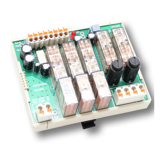
REA3 Version 1.2
REA3 Safety switch conforming to
EN81-20 5.6.7 "UCM" for
"Prevention of unintended travel
of a lift"
General information:
The safety switch REA3 is intended for use in safety circuits on a lift.
It consists of a fail-safe control module and corresponding sensors and/or magnetic switches.
The control for the brake element of the protective device is incorporated in the control module.
However, the brake element of the protective device itself is not part of this safety switch and/or
description and must be provided on the lift system by the customer.
Devices that have been tested according to the regulations of EN81, UCM and can bring the lift to a
standstill within the prescribed distance are used as the braking element of the protective unit.
Brief description:
The safety switch REA3 recognises unintended travel of the cabin when the doors are open and
switches off safely in case of an error.
Advantages and characteristics:
•
Automatic adjustment to the applied safety circuit voltage in a wide range from 48VAC to
230VAC. (24VDC – 230VDC)
•
Both magnetic switches are monitored for errors – when closing and opening.
•
The opening of the switch contact of the reset button is monitored.
•
The relevant safety circuit is tested with each status change.
•
Display of all important functions with 5 green LEDs
•
A red LED blinks in case of an error.
Safety switch REA3,
Variotech GmbH, Gewerbeweg 5, 2230 Gänserndorf, Tel +43 2282 60310, http://variotech.com
Variotech GmbH, Gewerbeweg 5, 2230 Gänserndorf, Tel +43 2282 60310, http://variotech.com
OPERATING INSTRUCTIONS AND DATA SHEET
Date:
17.08.2017
FOR SAFETY CONTROLLER REA3
,
Page 1 of 12
Advertisement
Table of Contents

Summary of Contents for Variotech REA3
-
Page 1: General Information
Brief description: The safety switch REA3 recognises unintended travel of the cabin when the doors are open and switches off safely in case of an error. -
Page 2: Table Of Contents
Scope of delivery: .......................... 1 1 Order information and spare parts: .................... 1 2 , Page 2 of 12 Safety switch REA3, Date: 17.08.2017 Variotech GmbH, Gewerbeweg 5, 2230 Gänserndorf, Tel +43 2282 60310, http://variotech.com Variotech GmbH, Gewerbeweg 5, 2230 Gänserndorf, Tel +43 2282 60310, http://variotech.com... -
Page 3: General Legal Notices
, Page 3 of 12 Safety switch REA3, Date: 17.08.2017 Variotech GmbH, Gewerbeweg 5, 2230 Gänserndorf, Tel +43 2282 60310, http://variotech.com Variotech GmbH, Gewerbeweg 5, 2230 Gänserndorf, Tel +43 2282 60310, http://variotech.com... -
Page 4: Intended Use
Intended use: The only acceptable application for the safety switch REA3 is for lift systems. The safety switch REA3 must only be used for the case defined in EN81 Annex 3, prevention of unintended movement of the cabin from a standstill. -
Page 5: Ambient Conditions
The safety switch is delivered in a top-hat rail housing. An unoccupied top-hat rail width of approx. 10cm is required for installation. If there is no space available in the switch cabinet, the REA3 safety switch can also be installed in an industrial plastic housing (IP65) at the factory. - Page 6 • 1x LED with the designation “ON” indicates the presence of a suitable 24V supply voltage. , Page 6 of 12 Safety switch REA3, Date: 17.08.2017 Variotech GmbH, Gewerbeweg 5, 2230 Gänserndorf, Tel +43 2282 60310, http://variotech.com Variotech GmbH, Gewerbeweg 5, 2230 Gänserndorf, Tel +43 2282 60310, http://variotech.com...
-
Page 7: Possible Sources Of Error
MS1/MS2 must be 1 second; otherwise, this is also recognised as an error and recorded. The REA3 safety switch will then deactivate and shut down due to the recorded error when the next safety circuit opens. -
Page 8: Supply Voltage Monitoring
The safety switch operates again after replacement of the fuse. , Page 8 of 12 Safety switch REA3, Date: 17.08.2017 Variotech GmbH, Gewerbeweg 5, 2230 Gänserndorf, Tel +43 2282 60310, http://variotech.com Variotech GmbH, Gewerbeweg 5, 2230 Gänserndorf, Tel +43 2282 60310, http://variotech.com... -
Page 9: Commissioning
The UCM error is deleted by pressing the external RESET button. Note: The error cannot be deleted with activation/deactivation of the voltage. After the reset button is pressed, a check of the REA3 safety controller and external connections takes place. -
Page 10: Magnetic Switch Error Functional Test
• If the red LED blinks, the recorded error can be deleted by pressing the external reset button and , Page 10 of 12 Safety switch REA3, Date: 17.08.2017 Variotech GmbH, Gewerbeweg 5, 2230 Gänserndorf, Tel +43 2282 60310, http://variotech.com... -
Page 11: Maintenance
(encoders) for the door zone and the necessary magnetic tape (2x 20cm per stop). The REA3 safety switch is delivered in a plastic housing for top-hat rail installation, and should be installed in a switch cabinet by the customer. On request, the device can also be supplied in an individual industrial plastic housing (IP65). -
Page 12: Order Information And Spare Parts
Mains adapter top-hat rails REA3_MDR 230V REA3 reset button with cable (length 2m) REA3-RES1 REA3 reset button for top-hat rail installation REA3-RES2 , Page 12 of 12 Safety switch REA3, Date: 17.08.2017 Variotech GmbH, Gewerbeweg 5, 2230 Gänserndorf, Tel +43 2282 60310, http://variotech.com...
Need help?
Do you have a question about the REA3 and is the answer not in the manual?
Questions and answers