Table of Contents
Advertisement
Quick Links
Advertisement
Table of Contents

Related Manuals for Marine Air Systems ECU-Maxx

Summary of Contents for Marine Air Systems ECU-Maxx
-
Page 2: Table Of Contents
..................12 ROGRAMMABLE ARAMETERS Soft Start Ramp Delay ..................18 De-Icing ......................... 19 ....................... 20 ROGRAM ABLE ....................21 HEORY OF PERATION ECU-Maxx System Timing ..................21 ................... 22 YSTEM IMING IAGRAM ..................23 YSTEM NPUTS AND UTPUTS ................. 25 SAFE... -
Page 3: Introduction
EATURES AC Voltmeter The ECU-Maxx's hardware includes an AC voltmeter which is used to monitor and display line voltage. These readings represent the voltage at the control module, not at the electrical panel. The line voltage feature is the first item accessed in the View Mode. -
Page 4: Solid State Fuses
When AC power is restored, the ECU-Maxx will resume operation exactly where it left off, even if it is years later. -
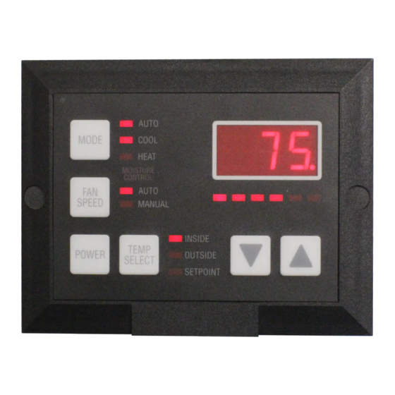
Page 5: Operator Controls & Display Panel
Please refer to Figure 1, below, for the location of the buttons and displays listed on the following pages: 1. POWER button The power button is used to switch the ECU-Maxx between Off Mode and On Mode, enter Program Mode and reset the Factory Default Values for the programmable parameters. - Page 6 ECU-Maxx. The decimal point to the far right on this display is used to indicate when the compressor is on.
-
Page 7: Modes Of Operation
All lights on the display will flash for one second before normal operation is resumed. Cool Only Mode When the ECU-Maxx is configured to be in Cool Only Mode, only the cooling system will be used as needed. Heat Only Mode When the ECU-Maxx is configured to be in the Heat Only Mode, only the heating system will be activated as necessary. -
Page 8: Fan Operation
Press the Power Button once to toggle the ECU-Maxx from On Mode to Off Mode. Note: The fan will remain on for 4 (four) minutes after the ECU-Maxx is turned off if heat was being supplied by the Optional CAL Rod Heater. -
Page 9: Basic Operation
All parameters are user-programmable. Adjusting the Set Point The Set Point should be set to the desired room temperature, as the ECU-Maxx will maintain temperature to within two degrees of the set point. The maximum setting for the set point is 85º F. The minimum setting for the set point is 60º F. - Page 10 Press and hold the Fan Speed Button to set the desired fan speed as indicated on the Fan Speed Bar Graph. The ECU-Maxx will enter Fan Only or Circulation Mode. Only the Fan Speed Bar Graph is illuminated during Circulation Mode.
-
Page 11: Program Mode
Operator confusion related to program parameters can also cause what seem to be operational problems. Whenever there is any doubt as to the proper operation of the ECU-Maxx control unit, factory default parameters should be initialized. Entering Program Mode Program Mode can only be entered from OFF Mode. -
Page 12: Using Program Mode
Exiting Program Mode There are two methods to exit program mode. Press the Power button and the ECU-Maxx returns to the OFF Mode. Not pressing any button for 60 (sixty) seconds will cause the control unit to exit Program Mode. - Page 13 Moisture Control Mode. The range for this value is between 95º F and 77º F. The room temperature where the ECU-Maxx display panel is located (unless a remote air Temp. Sensor has been installed) will not be allowed to exceed the temperature selected by this set point.
- Page 14 To help reduce head pressure, the automatic fan speed operation can be reversed in the heating mode. In other words, the fan speed increases as the set point is approached in heating mode. The fan speed spread option applies to this option. PAGE 14 ECU-Maxx VER:10a 12/1/97...
- Page 15 "H2O" in the display. Fail-safe protection levels apply to the low water limit. If the optional CAL rod heater is installed, the ECU-Maxx will automatically switch to the CAL rod heater when the water temperature is below the limit. The LO / H2O warning will not be displayed when the CAL rod heater is installed! The range for the low water limit setting is 40º...
- Page 16 The fault code "L-O" then "A-C" will flash alternately with the line voltage in the display. This function allows the ECU-Maxx to be used on a wide variety of line voltages. The allowable low voltage threshold range is 75 VAC through 100 VAC for 115 Volt units, and 175 VAC through 200 VAC for 220 Volt units.
- Page 17 . a fte r 4 fa ilure s. To restart ECU-Maxx manually, press the Power button to reset the unit to the OFF Mode. P24: Fail-safe Protection Level Fail-safe protection is offered at three levels, as enumerated in the table above.
-
Page 18: Soft Start Ramp Delay
Use the Up and Down buttons to adjust this setting. P28: Self Test The diagnostic self test is included to help verify proper operation of the ECU-Maxx. Upon entering the Test Mode, the following items are checked in the order shown. During the output checks, "P-28"... -
Page 19: Icing
This feature is used to calibrate the outside air sensor plus or minus 10 degrees Fahrenheit. Temperature Control Algorithm Note: Heating mode shown with automatic fan speeds reversed, i.e. P-12 ON … fan speed increases as set point is approached. PAGE 19 ECU-Maxx VER:10a 12/1/97... -
Page 20: Rogram Able
O ff = A nti Icin g D is able d P 3 4 C a lib ra te O utsid e A ir S e nso r 0 °F - 1 0 °F to + 1 0 °F PAGE 20 ECU-Maxx VER:10a 12/1/97... -
Page 21: Theory Of Operation
0 to 5 seconds. This delay may need adjustment for optimal results with your particular system. When Soft Start is enabled and the ECU-Maxx senses the need for heating or cooling, the following actions are taken: 1. -
Page 22: System Timing Diagram
ECU-M PERATIONS ANUAL YSTEM IMING IAGRAM PAGE 22 ECU-Maxx VER:10a 12/1/97... -
Page 23: System Inputs And Outputs
The water temperature must be greater than the low water limit to activate the valve, if the optional CAL rod heater has been installed. The compressor output is on when the ECU-Maxx is calling for heating or COMP. cooling. The compressor is not on in the heating mode if heat is being supplied by the optional electric CAL rod heater. - Page 24 ECU-M ECU-M PERATIONS ANUAL NPUTS AND UTPUTS PAGE 24 ECU-Maxx VER:10a 12/1/97...
-
Page 25: Fail - Safe And Fault Handling
Fault Code Action Taken by ECU-Maxx Level 1 Leve Air Sensor Fault Complete shutdown until the fault is cleared. Water Sensor Fault Shutdown of water pump until the fault is cleared. High Pressure Fault Shutdown of compressor until the fault is cleared. -
Page 26: Fault Handling & Fail - Safe Modes
This resets the control but does not remove the fault! Electrical Short Faults When a short is detected on one of the system output terminals, the ECU-Maxx will display the fault code "SHO" followed by another code indicating which output is shorted: "CO"... -
Page 27: 416 Option Board
ANUAL 416 O PTION OARD An Optional Accessory Board may be ordered for the ECU-Maxx [Part Number: 416-X0A]. This board provides inputs for the following features: • Auxiliary Heater (CAL Rod Heater) • Outside Air Sensor • Service / Water Sensor... -
Page 28: Typical Application
ECU-M PERATIONS ANUAL YPICAL PPLICATION PAGE 28 ECU-Maxx VER:10a 12/1/97... -
Page 29: Specifications
40 AMP S a t 2 20 VAC C AL R OD H E AT E R 30 AMP S a t 2 20 VAC (4 16 O ption B oa rd R e q uired ) PAGE 29 ECU-Maxx VER:10a 12/1/97... -
Page 30: Factory Programming Options F-1 Through F-8
Shutting down the compressor and flashing SCR saves unnecessary compressor burnouts. SCR is NORMALLY ON and can be tempo- rarily turned off for trouble shooting, however, SCR should be turned on after the problem is resolved. PAGE 30 ECU-Maxx VER:10a 12/1/97... -
Page 31: Revision History
PERATIONS ANUAL REVISION HISTORY Revision: 08 First revision from Wendy's original manual. Update from original ECU-Maxx to Software versions 2.7 through 3.5. Corrected wiring diagrams, program tables and general contents. Revision: 09 Changed page 28 typical application to reflect new PC board. Changed P16 and P17 descriptions to include default settings to ON.