
Related Manuals for GHM Delta OHM LPPYRA13


Summary of Contents for GHM Delta OHM LPPYRA13
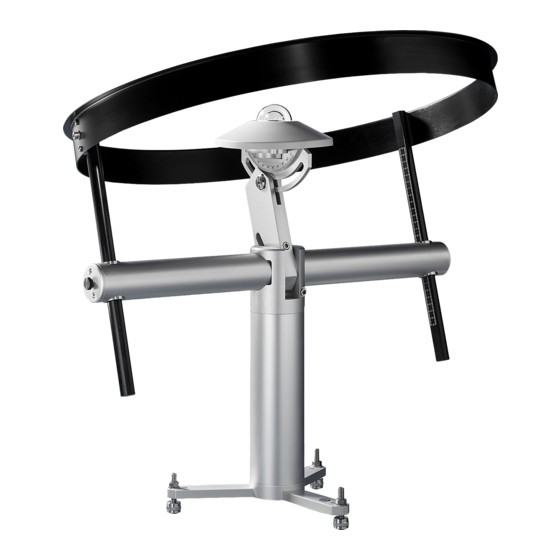
- Page 1 English Operating manual Pyranometer LPPYRA13 Companies / Brands of GHM www.deltaohm.com Keep for future reference.
-
Page 2: Table Of Contents
TABLE OF CONTENTS INTRODUCTION ....................3 WORKING PRINCIPLE ................... 4 INSTALLATION ..................... 6 ................. 7 OUNTING THE SHADOW RING ......8 OSITIONING THE INSTRUMENT FOR THE DIFFUSE RADIATION MEASUREMENT ELECTRICAL CONNECTIONS ................12 LPPYRA13 ................... 12 CONNECTIONS LPPYRA13AC ................13 CONNECTIONS LPPYRA13AV ................ -
Page 3: Introduction
INTRODUCTION LPPYRA13 pyranometer measures the irradiance on a flat surface (W/m ). Thanks to the shadow-ring, LPPYRA12 measures the diffuse solar radiation eliminating the con- tribution of direct irradiance. LPPYRA13 is equipped with a Spectrally Flat Class A (Secondary Standard) pyranome- ter (LPPYRA10) in accordance with ISO 9060:2018 and with the criteria of the WMO “Guide to Meteorological Instruments and Methods of Observation”. -
Page 4: Working Principle
2 WORKING PRINCIPLE LPPYRA13 pyranometer is based on a thermopile sensor. The thermopile sensitive sur- face is coated with a black matt paint, which allows the pyranometer not to be selec- tive at different wavelengths. In order to grant the thermopile a proper thermal insulation from the wind and reduce the sensitivity to thermal irradiance, LPPYRA13 is equipped with two concentric domes having 50 mm and 32 mm outer diameter. - Page 5 Temperature (°C) Fig. 2.2: : percentage change of LPPYRA13 pyranometer sensitivity in the temperature range -20…50 °C compared to the sensitivity at 20 °C The shadow ring prevents the direct solar radiation to reach the sensor the whole day long, so that only the diffuse solar radiation will be measured. Because the elevation of the sun changes day by day, it is necessary to change the height of the shad- ow ring at least every two days.
-
Page 6: Installation
3 INSTALLATION Before installing the pyranometer, refill the cartridge containing silica-gel crystals. Sil- ica gel absorbs humidity in the dome chamber and prevents, in particular climatic conditions, condensation on the internal walls of the domes and measurement altera- tion. Do not touch the silica gel crystals with your hands while refilling the cartridge. Carry out the following instructions in an environment as drier as possible: 1. -
Page 7: Mounting The Shadow Ring
• The pyranometer must be mounted in an easy-to-reach location in order to clean the dome regularly and carry out maintenance. At the same time, make sure that no buildings, constructions, trees or obstructions exceed the horizontal plane where the pyranometer lies. If this is not possible, select a site where obstructions in the path of the sun from sunrise to sunset do not exceed 5 degrees of elevation. -
Page 8: Positioning The Instrument For The Diffuse Radiation Measurement
3.2 P OSITIONING THE INSTRUMENT FOR THE DIFFUSE RADIATION MEASUREMENT The shadow ring particular geometry allows intercepting the solar direct radiation dur- ing the whole day without adjustments. The base of the instrument has to be mounted parallel to the ground by adjusting the screw with ring nut and with the aid of the levelling device integrated in the instrument. - Page 9 Adjusting the shadow ring tilt: 1. Check that the sliding bars and the long side of the pyranometer support be parallel (instruments are supplied factory aligned). 2. Mount and fix the pyranometer to the goniometer. 3. Position the goniometer in such a way to read on its scale the latitude of the instal- lation site.
- Page 10 TABLE 1A VALID ONLY FOR LPPYRA13 (no AC/AV/S/S12 versions) The table shows the values to which the graduated sliding bars must be set for the different solar declinations and for the two hemispheres. Value to be set on the Value to be set on the Date Solar sliding bars (mm) if...
- Page 11 TABLE 1B VALID FOR LPPYRA13AC / LPPYRA13AV / LPPYRA13S / LPPYRA13S12 The table shows the values to which the graduated sliding bars must be set for the different solar declinations and for the two hemispheres. Value to be set on the Value to be set on the Date Solar...
-
Page 12: Electrical Connections
4 ELECTRICAL CONNECTIONS LPPYRA13, LPPYRA13AC and LPPYRA13AV have a 4-pole connector and use the CPM12AA4... optional cables in UV resistant PTFE, with 4-pole connector on one side and open wires on the other side. LPPYRA13S and LPPYRA13S12 have a 8-pole connector and use the CPM12-8D... optional cables in UV resistant PTFE, with 8-pole connector on one side and open wires on the other side. -
Page 13: Lppyra13Ac Connections
4.2 LPPYRA13AC CONNECTIONS The pyranometer LPPYRA13AC has 4…20 mA output and requires 10…30 Vdc exter- nal power supply. It is to be connected to a power supply and an instrument with 4…20 mA input as shown in fig. 4.2. The load resistance of the instrument reading the signal must be ≤... -
Page 14: Lppyra13S Connections
4.4 LPPYRA13S CONNECTIONS The pyranometer LPPYRA13S has RS485 Modbus-RTU output and requires 5…30 Vdc external power supply. It is to be connected to a power supply and to a PLC, a data logger or a RS485/USB or RS485/RS232 converter for PC as shown in fig. 4.4. -
Page 15: Lppyra13S12 Connections
4.5 LPPYRA13S12 CONNECTIONS The pyranometer LPPYRA13S12 has SDI-12 output and requires 7…30 Vdc external power supply. It is to be connected to a power supply and to an acquisition system (data logger) as shown in fig. 4.5. Connector Function Cable color Power supply negative (GND) Blue SDI-12 output negative... -
Page 16: Measurement In The Models With Analog Output
5 MEASUREMENT IN THE MODELS WITH ANALOG OUTPUT Below are the ways to calculate the global irradiance in the models with analog output LPPYRA13, LPPYRA13AC and LPPYRA13AV. 5.1 LPPYRA13 Each pyranometer is distinguished by its own sensitivity (or calibration factor) S ex- pressed in µV/(Wm ) and shown in the label on the pyranometer (and in the calibra- tion report). -
Page 17: Rs485 Modbus-Rtu Output
6 RS485 MODBUS-RTU OUTPUT Before connecting the pyranometer to the RS485 network, an address must be assigned and the communication parameters must be set, if different from the factory preset. 6.1 S ETTING THE COMMUNICATION PARAMETERS Connect the pyranometer to the PC in one of the following two ways: A. - Page 18 4. Within 10 seconds from the pyranometer power on, send the @ command and press Enter. Note: if the pyranometer does not receive the @ command within 10 seconds from power on, the RS485 MODBUS mode is automatically activated. In such a case, it is necessary to switch off and on again the pyranometer.
-
Page 19: Reading The Measures With The Modbus -Rtu Protocol
6.2 R -RTU EADING THE MEASURES WITH THE ODBUS PROTOCOL In MODBUS mode, you can read the values measured by the pyranometer through the function code 04h (Read Input Registers). The following table lists the quantities available with the appropriate register address: Number Address Quantity... -
Page 20: Sdi-12 Output
7 SDI-12 OUTPUT The LPPYRA13S12 pyranometers are compatible with version 1.3 of SDI-12 protocol. The protocol communication parameters are: Baud rate = 1200. Data bits = 7, Parity = Even, Stop bits = 1. The communication with the instrument is performed by sending a command in the following form: <Address><Command>! with <Address>... - Page 21 Command Instrument reply Description a<CR><LF> Request of the address of the instrument. If more than one sensor is connected to the bus, a conflict occurs. START MEASUREMENT AND TYPE START CONCURRENT MEASUREMENT COMMANDS Irradiance, signal internal level and internal temperature (if available) atttn<CR><LF>...
- Page 22 Command Instrument reply Description Internal temperature (if available) aM2! atttn<CR><LF> Request to execute the measurement. aC2! with: ttt = number of seconds necessary for the in- strument to make the measure available (3 characters) n = number of detected variables (1 character for aM2!, 2 characters for aC2!) Note: ttt = 000 means datum immediately available.
- Page 23 The extended commands allow setting the temperature unit of measurement (if the temperature sensor is present). To change the unit of measurement: 1) Send the command aXSCAL USER ON! (note: a=instrument address). 2) Send the command aXSCFD! (to set °C) or aXSCFE! (to set °F). 3) Send the command aXSCAL END! For more information about the SDI-12 protocol, visit the website "www.sdi-12.org".
-
Page 24: Measurement Correction
8 MEASUREMENT CORRECTION Diffuse radiation is measured by eliminating the contribution of direct radiation through the shadow ring. As besides the direct radiation the shadow ring intercepts part of the diffuse light, it is necessary to correct the measured values. The percentage of diffuse radiation intercepted by the shadow ring changes during the year, because the position that the ring has with respect to the pyranometer changes. - Page 25 TABLE 2 Correction factor C for installation in the Northern hamisphere. Northern latitude Solar declination 1.11 1.10 1.09 1.09 1.08 1.07 1.06 1.05 1.04 1.03 1.11 1.11 1.10 1.09 1.08 1.07 1.06 1.05 1.04 1.03 1.12 1.11 1.10 1.10 1.09 1.08 1.07 1.06...
- Page 26 TABLE 3 Correction factor C for installation in the Southern hamisphere. Southern latitude Solar declination 1.11 1.10 1.09 1.09 1.08 1.07 1.06 1.05 1.04 1.03 1.11 1.11 1.10 1.09 1.08 1.07 1.06 1.05 1.04 1.03 1.12 1.11 1.10 1.10 1.09 1.08 1.07 1.06...
-
Page 27: Maintenance
9 MAINTENANCE In order to grant measurements high accuracy, it is important to keep the outer glass dome clean. Consequently, the more the dome will be kept clean, the more measure- ments will be accurate. You can wash it using water and standard papers for lens. If necessary, use pure ETHYL alcohol. -
Page 28: Technical Specifications
10 TECHNICAL SPECIFICATIONS Sensor Thermopile Typical sensitivity 6÷11 µV/Wm- Impedance 5÷50 Ω Measuring range 0÷2000/4000 W/m Viewing angle 2π sr Spectral range (50%) 283÷2800 nm Operating temperature/humidity -40÷80 °C / 0÷100% Output Analog in µV/Wm- (LP PYRA10) Analog 4÷20 mA (LPPYRA13AC) Analog 0÷1 V, 0÷5 V or 0÷10 V (LPPYRA13AV) Digital RS485 Modbus-RTU (LPPYRA13S) Digital SDI-12 (LPPYRA13S12) -
Page 29: Safety Instructions
11 SAFETY INSTRUCTIONS General safety instructions The instrument has been manufactured and tested in accordance with the safety standard EN61010-1:2010 “Safety requirements for electrical equipment for meas- urement, control and laboratory use” and has left the factory in perfect safety tech- nical conditions. -
Page 30: Ordering Codes
12 ORDERING CODES LPPYRA13 Spectrally Flat Class A (Secondary Standard) pyranometer ac- cording to ISO 9060:2018 supplied with shadow ring for measuring the diffuse radiation only. Complete with shade disk, cartridge for silica-gel crystals, 2 spare sachets, levelling device, M12 4-pole connector and Calibration Report. - Page 31 CPM12-8D.5 Cable with 8-pole M12 connector on one end, open wires on the other end. Length 5 m. CPM12-8D.10 Cable with 8-pole M12 connector on one end, open wires on the other end. Length 10 m. CP24 PC connecting cable for the RS485 MODBUS parameters configu- ration of the LPPYRA…S pyranometers.
- Page 32 OTES LPPYRA13 V2.3...
- Page 33 OTES LPPYRA13 V2.3...
- Page 34 OTES LPPYRA13 V2.3...
- Page 36 G U A R A N T E E TERMS OF GUARANTEE All DELTA OHM instruments are subject to accurate testing, and are guaranteed for 24 months from the date of purchase. DELTA OHM will repair or replace free of charge the parts that, within the warranty period, shall be deemed non efficient according to its own judgement.
- Page 37 GHM GROUP – Delta OHM | Delta Ohm S.r.l. a socio unico Via Marconi 5 | 35030 Caselle di Selvazzano | Padova | ITALY Phone +39 049 8977150 | Fax +39 049 635596 www.deltaohm.com | info@deltaohm.com The quality level of our instruments is the result of the constant development of the product. This may produce some differences between the information written in this manual and the instrument you have purchased.
- Page 38 GHM GROUP – Delta OHM | Delta Ohm S.r.l. a socio unico Via Marconi 5 | 35030 Caselle di Selvazzano | Padova | ITALY Phone +39 049 8977150 | Fax +39 049 635596 www.deltaohm.com | info@deltaohm.com V2.3 10/09/2020...
Need help?
Do you have a question about the Delta OHM LPPYRA13 and is the answer not in the manual?
Questions and answers