Table of Contents
Advertisement
Quick Links
8LVA three-phase
synchronous motors
User's manual
Version: 1.0 (2017-06-06)
Model no.: MAMOT7-ENG
All information contained in this manual is current as of its creation/publication. We reserve the right to change
the contents of this manual without warning. The information contained herein is believed to be accurate as
of the date of publication; however, Bernecker + Rainer Industrie-Elektronik Ges.m.b.H. makes no warranty,
expressed or implied, with regard to the products or documentation contained within this manual. In addition,
Bernecker + Rainer Industrie-Elektronik Ges.m.b.H. shall not be liable for any incidental or consequential damages
in connection with or arising from the furnishing, performance or use of the product(s) in this documentation. Soft-
ware names, hardware names and trademarks are registered by their respective companies.
Advertisement
Table of Contents

Summary of Contents for Bernecker + Rainer MAMOT7-ENG
- Page 1 In addition, Bernecker + Rainer Industrie-Elektronik Ges.m.b.H. shall not be liable for any incidental or consequential damages in connection with or arising from the furnishing, performance or use of the product(s) in this documentation. Soft-...
-
Page 2: Table Of Contents
Table of contents 1 General information....................4 1.1 Manual history..............................4 1.2 About this user's manual..........................4 1.3 Safety................................4 1.3.1 Organization of safety notices........................4 1.3.2 Intended use..............................4 1.3.3 Reasonably foreseeable misuse....................... 5 1.3.4 General sources of danger........................5 1.3.5 Provisions and safety guidelines.......................7 1.3.6 Responsibilities of the operator.........................8 1.3.7 Qualified personnel............................8 1.3.8 Safety notices............................ - Page 3 Table of contents 2.11.4 Speed-Torque characteristic curve at 325 VDC DC bus voltage............34 3 Transport and storage....................35 3.1 Transport............................... 35 3.2 Storage................................36 4 Installation conditions.................... 37 4.1 Flange installation and cooling........................37 4.2 Load due to radial and axial force........................38 5 Installation and connection...................
-
Page 4: General Information
General information 1 General information 1.1 Manual history Version Date Comment Author 1.00 2017-06-06 First edition Docu 2 Information: B&R makes every effort to keep user's manuals as current as possible. New versions are made avail- able in electronic form on the B&R website at www.br-automation.com. Check regularly whether you have the latest version. -
Page 5: Reasonably Foreseeable Misuse
General information • It has been determined that the machine complies with the provisions of EC directive 2006/42/EC (Machin- ery Directive) and EMC Directive 2014/30/EU. • All values specified on the type plate and in the user's manual (e.g. connection and environmental condi- tions) have been observed. - Page 6 General information Danger! Risk of injury due to electric shock! There is an immediate risk of fatal injury in case of contact with live parts. If connections are connected or disconnected in the wrong order or under voltage, arcs can arise and persons and contacts can be damaged.
-
Page 7: Provisions And Safety Guidelines
General information Danger! Danger of injury due to rotating or moving elements and loads! By rotating or moving elements, body parts can be drawn in or severed or subjected to impacts. • Do not remain in a dangerous area during operation and secure it from access by unauthorized persons. -
Page 8: Responsibilities Of The Operator
General information • National, local and plant-specific regulations for your end product • Relevant regulations for electrical installations (e.g. cable cross-section, fuses, protective conductor con- nection). The values provided in chapter "Technical data" must also be taken into account here. The operator is solely responsible for these and all other regulations applicable at the place of use. -
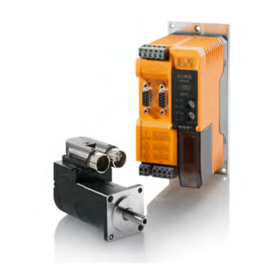
Page 9: 8Lva - Compact Servo Technology
General information 1.4 8LVA - Compact servo technology The 8LVA motor series is the perfect choice when it comes to in- stalling servo motors in extremely tight spaces. Equipped with either a resolver or digital EnDat 2.2 interface, these motors can meet the absolute highest demands. - Page 10 General information Routine service work is also simplified in addition to commissioning, and motors can be exchanged without having to take extra time to set parameters. 8LVA user's manual V1.0...
-
Page 11: Technical Data
Technical data 2 Technical data 2.1 General description The special construction of the surface allows them to be used in applications for the food and beverage industry. Depressions where liquid can collect were deliberately avoided. • Ultra compact and highly dynamic •... -
Page 12: Motor Encoder Systems
Technical data 2.2 Motor encoder systems General Motors in the 8LV series are available with EnDat encoders as well as resolvers. The encoder system is listed as part of the model number in the form of a 2-digit code (ee). Analog and digital transfer A resolver is an analog encoder system. - Page 13 Technical data EnDat 2.2 encoders - Technical data Encoder type / Order code (ee) Operating principle Inductive EnDat protocol EnDat 2.2 Single-turn / Multi-turn Battery-backed Revolutions 65536 4096 Resolution 18/16 19/0 19/12 [bits single-turn / bits multi-turn] Precision [''] Switching frequency ≥ [kHz] Digital pos.
-
Page 14: Motor Options
Technical data 2.3 Motor options Servo motors from the 8LV series are available in different variants depending on the customer's requirements: • With various motor encoders • With various nominal speeds • Available with double angular built-in connector or single-cable solution (hybrid) •... -
Page 15: Connection
Technical data 2.3.4 Connection In addition to the standard connection (double angular built-in connector), the single-cable solution (hybrid) is also available. Double angular built-in connector Single-cable solution For information about possible combinations, see the previous table. see "Motor options table" on page 14 2.3.5 Oil seal The 8LV servo motors in sizes 2 and 3 are available with an optional Form A oil seal in accordance with DIN 3760. -
Page 16: 8Lva - Order Key
Technical data Keyed shaft end A keyed shaft end is used for a form-fit torque transfer with low demands on the shaft- hub connection and for handling torque in a constant direction. The keyways for the servo motors in this series conform to keyway form N1 in accor- dance with DIN 6885-1. -
Page 17: Example Order 1
Technical data 2.4.1 Example order 1 A three-phase synchronous motor of type 8LVA22 with a nominal speed of 3000 rpm has been selected for an application. The connection should use a single-cable solution (hybrid). The motor should be equipped with a holding brake, a keyed shaft and an EnDat encoder. -
Page 18: General Motor Data
Technical data 2.5 General motor data General information Cooling type A CE certification C-UR-US listed UL file number PRHZ2.E235396 Electrical characteristics DC bus voltage on the ACOPOSmicro 80VDC Conventional connection type (power connection / encoder connection) ytec circular connector from Intercontec Connection type - Single-cable solution (hybrid) htec circular connector from Intercontec Thermal characteristics... -
Page 19: Power Dissipation
Technical data Term Symbol Unit Description Peak current The peak current is the RMS value of the phase current (current in the motor supply line) for generating the peak torque. This is only permitted to be drawn for a short time. The peak current is determined by the magnetic circuit. -
Page 20: 8Lva Standard Motors
Technical data 2.6 8LVA standard motors The 8LVA series includes a selection of sizes and options that represent pre- ferred types (standard motors). These standard motors feature an unbeatable price/performance ratio and much faster delivery times. If necessary, these motors can be ready on short notice and dispatched using express delivery. The following standard motors are available: •... -
Page 21: 8Lva1/8Lva2 - Product Overview
Technical data 2.7 8LVA1/8LVA2 - Product overview Size 1 and 2 Model number 8LVA13. 8LVA13. 8LVA22. 8LVA22. 8LVA23. 8LVA23. 8LVA23. ee015ffgg-0 ee030ffgg-0 ee015ffgg-0 ee030ffgg-0 eeA95ffgg-0 ee015ffgg-0 ee030ffgg-0 Motor Nominal speed n [rpm] 1500 3000 1500 3000 1500 3000 Number of pole pairs Nominal torque M [Nm] 0.34... -
Page 22: 8Lva3 - Product Overview
Technical data 2.8 8LVA3 - Product overview Size 3 Model number 8LVA33.ee005ffee-0 8LVA33.ee015ffgg-0 8LVA33.ee021ffgg-0 Motor Nominal speed n [rpm] 1500 2100 Number of pole pairs Nominal torque M [Nm] 2.45 Nominal power P Nominal current I Stall torque M [Nm] Stall current I Maximum torque M [Nm]... - Page 23 Technical data 8LVA user's manual V1.0...
-
Page 24: 8Lva1 - Technical Data
Technical data 2.9 8LVA1 - Technical data Size 1 Model number 8LVA13.ee015ffgg-0 8LVA13.ee030ffgg-0 Motor Nominal speed n [rpm] 1500 3000 Number of pole pairs Nominal torque M [Nm] 0.34 0.32 Nominal power P Nominal current I Stall torque M [Nm] 0.36 Stall current I Maximum torque M... -
Page 25: Maximum Shaft Load
Technical data 2.9.2 Maximum shaft load The values in the diagram below are based on a mechanical service life of the bearings of 20,000 operating hours. 1000 1500 3000 4500 6000 (smooth shaft) rmax (shaft key) Figure 1: Definition of shaft load rmax .. -
Page 26: Speed-Torque Characteristic Curve At 325 Vdc Dc Bus Voltage
Technical data 2.9.4 Speed-Torque characteristic curve at 325 VDC DC bus voltage ACOPOS (single phase) −1 = 1500 min −1 = 3000 min (0/1) (0/1) (4653/1) (6600/1) (6600/0.6) (0/0.4) (0/0.4) 1000 2000 3000 4000 5000 6000 7000 TChar version:0124 dT ... 100K −1 Speed in min DB version:2016 04 28... -
Page 27: 8Lva2 - Technical Data
Technical data 2.10 8LVA2 - Technical data Size 2 Model number 8LVA22.ee015ffgg-0 8LVA22.ee030ffgg-0 8LVA23.eeA95ffgg-0 8LVA23.ee015ffgg-0 8LVA23.ee030ffgg-0 Motor Nominal speed n [rpm] 1500 3000 1500 3000 Number of pole pairs Nominal torque M [Nm] 0.67 0.65 1.33 Nominal power P Nominal current I 1.61 2.02 Stall torque M... -
Page 28: Maximum Shaft Load
Technical data Single-cable solution EnDat/Resolver feedback Extension of K depending on motor option Holding brake Oil seal Encoder assignments R0, B1 B8, B9 R0, B1 B8, B9 8LVA22 85.5 90.5 8LVA23 IMPORTANT: Dimensions K and M depend on the length of the encoder cover. 2.10.2 Maximum shaft load The values in the diagram below are based on a mechanical service life of the bearings of 20,000 operating hours. -
Page 29: Speed-Torque Characteristic Curve At 80 Vdc Dc Bus Voltage
Technical data 2.10.3 Speed-Torque characteristic curve at 80 VDC DC bus voltage ACOPOSmicro −1 = 1500 min −1 = 3000 min (0/2) (0/2) (823/2) (2027/2) (0/0.7) (0/0.7) (3858/0.1) (2111/0) 1000 1500 2000 2500 3000 3500 4000 4500 TChar version:0124 dT ... 100K −1 Speed in min DB version:2016 04 28... -
Page 30: Speed-Torque Characteristic Curve At 325 Vdc Dc Bus Voltage
Technical data 2.10.4 Speed-Torque characteristic curve at 325 VDC DC bus voltage ACOPOS (single phase) −1 = 1500 min −1 = 3000 min (0/2) (0/2) (5346/2) (6600/2) (6600/2) (6600/1.3) (0/0.7) (0/0.7) 1000 2000 3000 4000 5000 6000 7000 8000 TChar version:0124 dT ... - Page 31 Technical data 8LVA user's manual V1.0...
-
Page 32: 8Lva3 - Technical Data
Technical data 2.11 8LVA3 - Technical data Size 3 Model number 8LVA33.ee005ffee-0 8LVA33.ee015ffgg-0 8LVA33.ee021ffgg-0 Motor Nominal speed n [rpm] 1500 2100 Number of pole pairs Nominal torque M [Nm] 2.45 Nominal power P Nominal current I Stall torque M [Nm] Stall current I Maximum torque M [Nm]... -
Page 33: Maximum Shaft Load
Technical data Single-cable solution EnDat/Resolver feedback Extension of K depending on motor option Model number Holding brake Oil seal Encoder assignments R0, B1 B8, B9 R0, B1 B8, B9 8LVA33 17.5 24.5 IMPORTANT: Dimensions K and M depend on the length of the encoder cover. 2.11.2 Maximum shaft load The values in the diagram below are based on a mechanical service life of the bearings of 20,000 operating hours. -
Page 34: Speed-Torque Characteristic Curve At 80 Vdc Dc Bus Voltage
Technical data 2.11.3 Speed-Torque characteristic curve at 80 VDC DC bus voltage ACOPOSmicro −1 = 500 min (0/7.2) (157/7.2) (0/7.2) (0/7.2) (1267/7.2) (1706/7.2) −1 = 1500 min −1 = 2100 min (0/2.6) (0/2.6) (0/2.6) (745/0) (2111/0) (2665/0) 1000 1500 2000 2500 3000 TChar version:0124... -
Page 35: Transport And Storage
Transport and storage 3 Transport and storage During transport and storage, the product must be protected against undue stress (mechanical loads, temperature, moisture, corrosive atmospheres, etc.). If necessary, also protect existing electrostatically sensitive components such as the encoders in motors against electrostatic discharge (ESD). -
Page 36: Storage
Transport and storage 3.2 Storage Warning! Damage caused by loss of material properties. Long storage or storage under improper conditions means that certain materials age prematurely, lose their properties and can be damaged. Damaged components can result in further property damage. Recommendations for the prevention of damage caused by storage: •... -
Page 37: Installation Conditions
Installation conditions 4 Installation conditions Before every commissioning procedure, the motor must be checked by qualified personnel. The check must include the proper condition in terms of mounting and installation, the installation conditions and safe operation. Operating conditions Rating class, operating mode in accordance with EN 60034-1 S1 - Continuous operation Ambient temperature during operation -15°C to +40°C... -
Page 38: Load Due To Radial And Axial Force
Installation conditions Warning! Personal injury and damage to property due to failure or overheating of the drive. If the maximum permissible operating temperature is exceeded, an arising drive defect with conse- quential damage is very probable. The cause of a defect could insufficient lubrication due to overheating, for example. •... - Page 39 Installation conditions Determining permissible values of F and F Information regarding determination of permissible values for F and F can be taken from the motor data for the respective three-phase synchronous motors (see section "Radial force diagram"). Permissible values are based on a bearing lifespan of 20,000 h (bearing lifespan calculation based on DIN ISO 281).
-
Page 40: Installation And Connection
Installation and connection 5 Installation and connection 5.1 Before installation Read this user's manual completely before performing any work activities. In addition, take into account the technical documentation for all other machine components as well as the finished machine. 5.2 Safety Assembly is only permitted to be carried out in a voltage-free condition and only by qualified personnel . - Page 41 Installation and connection Danger! Risk of injury due to electric shock! There is an immediate risk of fatal injury in case of contact with live parts. If connections are connected or disconnected in the wrong order or under voltage, arcs can arise and persons and contacts can be damaged.
- Page 42 Installation and connection Danger! Danger of injury due to rotating or moving elements and loads! By rotating or moving elements, body parts can be drawn in or severed or subjected to impacts. • Do not remain in a dangerous area during operation and secure it from access by unauthorized persons.
-
Page 43: Noise Emissions
Installation and connection Danger! Risk of burns due to hot surfaces! Touching hot surfaces (e.g. motor and gearbox housings, as well as connected components), can lead to very severe burns due to the very high temperature of these parts. • Do not remain in a dangerous area during operation and secure it from access by unauthorized persons. - Page 44 Installation and connection Installing and removing attachment elements Always install and remove the attachment elements (gears, pulleys, couplings, etc.) at the shaft end without any axial load on the motor bearings and all other parts installed in the motor. For this, use suitable clamping sets, pressure sleeves, other tensioning elements, retractors, etc.
-
Page 45: Installing In The System
Installation and connection 5.4 Installing in the system Before working on motors, gearboxes or servo drives or in the danger zone of your machine, disconnect them completely from the power system and secure them against being switched on again by other persons or automatic systems. -
Page 46: Connecting And Disconnecting The Motor
Installation and connection 5.5 Connecting and disconnecting the motor Observe the following safety guidelines and instructions when connecting and disconnecting the motor: The protective conductor must be connected via the power connection or motor plug. Danger! Personal injury and property damage due to missing ground potential! If there is no proper grounding potential on the motor housing or servo drive, fault currents can lead to serious personal injury and property damage. -
Page 47: Cables And Connectors
Installation and connection Danger! Risk of burns due to hot surfaces! Touching hot surfaces (e.g. motor and gearbox housings, as well as connected components), can lead to very severe burns due to the very high temperature of these parts. • Do not remain in a dangerous area during operation and secure it from access by unauthorized persons. -
Page 48: Connection Sequence
Installation and connection • Cable support: A = max. 300 mm along longitudinal axis of connector • The connection must be free of force and torque. • Movement relative to the connector is not permitted! Note: For additional technical data and order data for the cables, see the current user's manual for the ACOPOS system being used. -
Page 49: Ensure Proper Connections
Installation and connection 5.5.3 Ensure proper connections Caution! Damage due to improper connector installation! Misalignment and subsequent pulling can cause disturbances and damage to the motor! • Ensure that connectors are installed and connected properly. 5.5.3.1 Double angular built-in connector The double angular built-in connector is equipped with a self-locking quick-release fastener. -
Page 50: Connection Type
Installation and connection 5.5.4 Connection type 5.5.4.1 Double angular built-in connector • 300° swivel double angular built-in connector • Quick-release self-locking connector system • Robust industrial connectors with optimal EMC shielding • Robust metal housing 5.5.4.1.1 Resolver connection - Pinout Pin Description Function Reference signal inverted... - Page 51 Installation and connection Encoder connectors Power connectors ytec Color Connectors Encoder connectors Green 42 mm 18.7 mm Power connectors Orange 42 mm 18.7 mm 8LVA user's manual V1.0...
- Page 52 Installation and connection 5.5.4.2 Single-cable solution (hybrid) • 300° swivel connector • Encoder and power conductor in one cable • Quick-release self-locking connector system • Robust industrial connectors with optimal EMC shielding • Robust metal housing Note: The following conditions must be met by the drives in order to operate a motor with a hybrid connector. •...
-
Page 53: Commissioning And Operation
Commissioning and operation 6 Commissioning and operation 6.1 Before commissioning and operation Read this user's manual completely before starting any commissioning activities or operation. In addition, take into account the technical documentation for all other machine components (e.g. servo drive) as well as the finished machine. - Page 54 Commissioning and operation Danger! Risk of injury due to electric shock! There is an immediate risk of fatal injury in case of contact with live parts. If connections are connected or disconnected in the wrong order or under voltage, arcs can arise and persons and contacts can be damaged.
- Page 55 Commissioning and operation Danger! Danger of injury due to rotating or moving elements and loads! By rotating or moving elements, body parts can be drawn in or severed or subjected to impacts. • Do not remain in a dangerous area during operation and secure it from access by unauthorized persons.
-
Page 56: Reversing Operation
Commissioning and operation Danger! Risk of burns due to hot surfaces! Touching hot surfaces (e.g. motor and gearbox housings, as well as connected components), can lead to very severe burns due to the very high temperature of these parts. • Do not remain in a dangerous area during operation and secure it from access by unauthorized persons. -
Page 57: Verification
Commissioning and operation Danger! Personal injury and damage to property due to non-intended use of the holding brake! If the holding brake is used differently than intended, functional failures and accidents involving per- sonal injury or damage to property are possible. •... -
Page 58: To Verify During Commissioning
Commissioning and operation 6.3.2 To verify during commissioning During commissioning, check that • the functionality of all motor attachments (protective equipment, encoder, brake, cooling, etc.) has been verified. • the operating conditions (see chapter "Installation conditions") are observed. • the brake (if present) is released. •... - Page 59 Commissioning and operation • Order description and serial number (see type plate) • Type and extent of fault • Circumstances under which the fault occurred • Application data (cycle of torque, speed and forces over time, environmental conditions) 8LVA user's manual V1.0...
-
Page 60: Inspection And Maintenance
Inspection and maintenance 7 Inspection and maintenance Various operating conditions (e.g. operating mode, temperature, speed, load, mounting orientation), can have a significant impact on the service life of lubricants, seals and bearings. Depending on the degree of pollution present, carry out periodic cleaning in order to ensure the removal of heat loss, among other things. - Page 61 Inspection and maintenance Danger! Risk of injury due to electric shock! There is an immediate risk of fatal injury in case of contact with live parts. If connections are connected or disconnected in the wrong order or under voltage, arcs can arise and persons and contacts can be damaged.
- Page 62 Inspection and maintenance Danger! Danger of injury due to rotating or moving elements and loads! By rotating or moving elements, body parts can be drawn in or severed or subjected to impacts. • Do not remain in a dangerous area during operation and secure it from access by unauthorized persons.
-
Page 63: Motor Bearing And Holding Brake
Inspection and maintenance Danger! Risk of burns due to hot surfaces! Touching hot surfaces (e.g. motor and gearbox housings, as well as connected components), can lead to very severe burns due to the very high temperature of these parts. • Do not remain in a dangerous area during operation and secure it from access by unauthorized persons. -
Page 64: Oil Seal
Inspection and maintenance Danger! Personal injury and damage to property due to non-intended use of the holding brake! If the holding brake is used differently than intended, functional failures and accidents involving per- sonal injury or damage to property are possible. •... -
Page 65: Disposal
Disposal 8 Disposal Separation of materials It is necessary to separate different materials so the device can undergo an environmentally friendly recycling process. Disposal must comply with applicable legal regulations. Component Disposal Note Motors Electronic recycling A magnetized rotor must never be transported or delivered outside the stator! Gearbox (without oil) Metal waste Waste oil (gearbox)
Need help?
Do you have a question about the MAMOT7-ENG and is the answer not in the manual?
Questions and answers