Table of Contents
Advertisement
Quick Links
General Warranty
Lilliput warrants that the product will be free from defects in materials and workmanship
for a period of 3 years (1 year for accessories) from the date of purchase of the product
by the original purchaser from the Lilliput Company. This warranty only applies to the
original purchaser and is not transferable to the third party. If the product proves
defective during the warranty period, Lilliput either will repair the defective product
without charge for parts and labor, or will provide a replacement in exchange for the
defective product. Parts, modules and replacement products used by Lilliput for warranty
work may be new or reconditioned like new performance. All replaced parts, modules
and products become the property of Lilliput.
In order to obtain service under this warranty, Customer must notify Lilliput of the defect
before the expiration of the warranty period. Customer shall be responsible for
packaging and shipping the defective product to the service center designated by Lilliput,
and with a copy of customer proof of purchase.
This warranty shall not apply to any defect, failure or damage caused by improper use or
improper or inadequate maintenance and care. Lilliput shall not be obligated to furnish
service under this warranty a) to repair damage resulting from attempts by personnel
other than Lilliput representatives to install, repair or service the product; b) to repair
damage resulting from improper use or connection to incompatible equipment; c) to
repair any damage or malfunction caused by the use of non-Lilliput supplies; or d) to
service a product that has been modified or integrated with other products when the
effect of such modification or integration increases the time or difficulty of servicing the
product.
Please contact the nearest Lilliput's Sales and Service Offices for services or a complete
copy of the warranty statement.
For better after-sales service, please visit www.owon.com.cn and register the purchased
product online.
Excepting the after-sales services provided in this summary or the applicable warranty statements,
Lilliput will not offer any guarantee for maintenance definitely declared or hinted, including but not
limited to the implied guarantee for marketability and special-purpose acceptability. Lilliput should
not take any responsibilities for any indirect, special or consequent damages.
For more details, please refer to the user manual on the supplied CD, it can also be
downloaded at www.owon.com.cn .
Advertisement
Table of Contents

Summary of Contents for Liliput XDM Series
- Page 1 General Warranty Lilliput warrants that the product will be free from defects in materials and workmanship for a period of 3 years (1 year for accessories) from the date of purchase of the product by the original purchaser from the Lilliput Company. This warranty only applies to the original purchaser and is not transferable to the third party.
-
Page 2: Table Of Contents
Table of Contents 1.Safety Information ....................1 Safety Terms and Symbols ....................1 General Safety Requirements ....................2 Measurement Limits ......................3 Main Input Terminals (HI Input and LO Input) Measurement Limits ............3 Current Input Terminal (I) Measurement Limits ..................3 Sense Terminals (HI Sense and LO Sense) Measurement Limits .............. -
Page 3: Safety Information
1.Safety Information 1. Safety Information Safety Terms and Symbols Safety Terms Terms in this Manual. The following terms may appear in this manual: Warning: Warning indicates the conditions or practices that could result in injury or loss of life. Caution: Caution indicates the conditions or practices that could result in damage to this product or other property. -
Page 4: General Safety Requirements
1.General Safety Requirements General Safety Requirements Before any operations, please read the following safety precautions to avoid any possible bodily injury and prevent this product or any other products connected from damage. In order to avoid any contingent danger, this product is only used within the range specified. -
Page 5: Measurement Limits
1.General Safety Requirements Measurement Limits The protection circuitry of the multimeter can prevent damage to the instrument and protect against the danger of electric shock, when the Measurement Limits are not exceeded. To ensure safe operation of the instrument, do not exceed the Measurement Limits shown on the front panel, it is defined as follows: The user-replaceable 10 A current-protection fuse is on the front panel. -
Page 6: Sense Terminals (Hi Sense And Lo Sense) Measurement Limits
1.General Safety Requirements same voltage as the LO Input terminal, unless a current protection fuse is open. Sense Terminals (HI Sense and LO Sense) Measurement Limits The HI and LO sense terminals are used for four-wire resistance measurements. The Measurement Limit from HI Sense to LO Input is 200 Vpk. The Measurement Limit from HI Sense to LO Sense is 200 Vpk. -
Page 7: Quick Start
2.Quick Start 2. Quick Start General Inspection After you get a new multimeter, it is recommended that you should make a check on the instrument according to the following steps: 1. Check whether there is any damage caused by transportation. If it is found that the packaging carton or the foamed plastic protection cushion has suffered serious damage, do not throw it away first till the complete device and its accessories succeed in the electrical and mechanical property tests. -
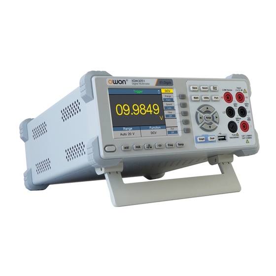
Page 8: Foot Stool Adjustment
2.Quick Start 295 mm Foot Stool Adjustment Unfold the foot stool on the bottom of the multimeter. Front Panel Overview Figure 2-1 Front panel overview Item Name Description Display the user interface Menu selection Activate the corresponding menu Keys Operation Keys Save Collect data in manual logging. - Page 9 2.Quick Start Math Perform math operations (statistic, limits, dB/dBm, REL) on the measurement results. Utility Set the auxiliary system function, including language, backlight, clock, trigger, set to default, system information, LCD test, key test. Port Set Serial, SCPI, Output connector, Net Type. HI and LO Sense Signal input terminals, used for four-wire resistance Terminals...
-
Page 10: Rear Panel Overview
2.Quick Start Graph Choose what is displayed: number, bar meter, trend chart, or histogram. Dual Push this key to display the function list on the right menu, select a function, if the function is supported, the reading will be displayed in the Vice Display. USB Port Connect with an external USB device, such as connect a USB device to the instrument. -
Page 11: User Interface
2.Quick Start AC Mains Line Select a proper voltage scale according to the AC supply Voltage Selector used. Switch between 110 V and 220 V. Line Fuse Use the specified fuse according to the voltage scale. To replace the fuse, see page 16, Appendix C: Line Fuse Replacement. -
Page 12: Ac Power Input Setting
2.Quick Start Main display function Main display reading Vice display reading Figure 2-4 User interface (Dual display) AC Power Input Setting Adopt 100 - 120 VAC or 220 - 240 VAC power source. Users should regulate the voltage scale of the AC Mains Line Voltage Selector according to the standards in their own country (see Figure 2-2 Rear panel overview) at the rear panel, and use an appropriate fuse. -
Page 13: Measurement Connections
2.Quick Start Measurement Connections After selecting the desired measurement function, please connect the signal (device) under test to the multimeter according to the method below. To avoid instrument damage, do not discretionarily switch the measurement function when measuring. DC Voltage Measurement AC Voltage Measurement DC Voltage AC Voltage... -
Page 14: Data Logging Function
2.Quick Start Capacitance Measurement Frequency/Period Measurement Capacitance AC Signal Temperature Measurement Temp Transducer Data Logging Function Data logging function includes manual logging and auto logging. You can use any or both functions to log the data. Manual logging: Press the front panel key to save current reading to volatile memory. -
Page 15: Auto Logging
2.Quick Start 3. Save the manual log in volatile memory: Press the Memory softkey to select internal or external memory. Press the Save softkey to save the manual log in volatile memory into the specified memory as a CSV file. (The existing file of manual log in the internal or external memory will be overwritten. -
Page 16: Troubleshooting
2.Quick Start Press the Memory softkey to select internal or external memory. Press the Display softkey to select Table or Graph to display the readings. Press the Read softkey to read and view the auto log file in the specified memory. (If the data is viewed in table, press keys to turn the page.) Auto logging data displayed in graph... -
Page 17: Appendix
3.Appendix 4) Check whether the DCI measurement function is used to measure AC current. If you encounter other problems, try to reset the settings or restart the instrument. If it still can not work properly, please contact LILLIPUT for our service, and provide your device information. -
Page 18: Appendix C: Line Fuse Replacement
3.Appendix liquids, or solvents. Warning: Before power on again for operation, it is required to confirm that the instrument has already been dried completely, avoiding any electrical short circuit or bodily injury resulting form the moisture. Appendix C: Line Fuse Replacement The line fuse is in the plastic fuse box below the power line input on the rear panel.
Need help?
Do you have a question about the XDM Series and is the answer not in the manual?
Questions and answers