
Related Manuals for NUVE KN 72

Summary of Contents for NUVE KN 72
- Page 1 NÜVE SANAYİ MALZEMELERİ İMALAT VE TİCARET A.Ş. KN 72/KN 120/KN 294/KN 504 BLOOD BANK REFRIGERATORS USER’S MANUAL 1984 Z14.K 25 253 Rev. No: 07 Rev. Date: 01/2016...
- Page 2 NÜVE SANAYİ MALZEMELERİ İMALAT VE TİCARET A.Ş. Saracalar Mah. Saracalar Kümeevleri No: 4/2 Akyurt 06750 Ankara Ankara / TURKEY : (90.312) 399 28 30 (pbx) : (90.312) 399 21 97 Sales : sales@nuve.com.tr Technical Service: nuveservice@nuve.com.tr...
- Page 3 INFORMATION CONTAINED IN THIS DOCUMENT IS THE PROPERTY OF NÜVE. IT MAY NOT BE DUPLICATED OR DISTRIBUTED WITHOUT PERMISSION. PLEASE REGISTER ONLINE TO VALIDATE YOUR WARRANTY: To register your warranty online, please visit our webpage www.nuve.com.tr and fill in the “Warranty Registration Form”.
-
Page 4: Table Of Contents
MOUNTING REMOTE ALARM ......................... 23 10.3. CHART RECORDER ..........................24 ELECTRICAL CIRCUIT DIAGRAM ........................25 11.1. KN 72 AND KN 120 ELECTRICAL CIRCUIT DIAGRAM ................25 11.2. KN 294 ELECTRICAL CIRCUIT DIAGRAM ....................26 11.3. KN 504 ELECTRICAL CIRCUIT DIAGRAM ....................27... -
Page 5: Introduction
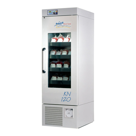
1.1. USE AND FUNCTION KN 72, KN 120, KN 294, KN 504 Blood Bank Refrigerators are designed for the storage of blood and all blood components. Besides its usage for the storage of blood in blood banks, they can be used for any cooling application in the allowed temperature range. -
Page 6: Technical Specifications
2. TECHNICAL SPECIFICATIONS 2.1. TECHNICAL SPECIFICATIONS TABLE TECHNICAL SPECIFICATIONS KN 72 KN 120 KN 294 KN 504 Temperature Range 0.0°C - 10.0°C Temperature Sensor Pt-100 Temperature Setting And 0.1°C Reading Sensitivity Thermostat Sensitivity ± 0.1°C Temperature Homogeneity ± 1°C ± 1.5°C at 4°C... -
Page 7: Accessories
KN series refrigerators have separators to hold blood bags in the upright position. These separators divide each shelf into 6 parts for KN 72 and KN 120 and each part contains 4 blood bags. As for KN 294 and KN 504, there are 7 partitions for each shelf and the capacity of each partition is 7 blood bags in the upright position. -
Page 8: Symbols And Labels
This symbol refers to important circumstances. Labels on the products: Earthed Wall Sockets KN 72 / KN 120 / KN 294 Fuses (2 x 10 A) KN 504 Fuses (2 x 13 A) 5. INSTALLATION 5.1. ENVIRONMENTAL CONDITIONS The instrument is designed to operate safely under the following conditions: ... -
Page 9: Unpacking
5.3. UNPACKING Remove the cardboard box packing and the second nylon wrapping around the instrument. Ensure that no damage has occurred during transport. The below mentioned are provided with the instrument, please check them; 1 ea. user’s manual and warranty ... -
Page 10: General Presentation
5.6. GENERAL PRESENTATION CONTROL PANEL POWER SWITCH KEY LOCK COMMUNICATION UNIT EXTERNAL PROBE ACCESS PORT DRAWER DOOR HANDLE GLASS DOOR DOOR LOCK CHART RECORDER Figure 1... -
Page 11: Control Panel
USB PORT-1 USB PORT-2 ETHERNET RS 232 Figure 2 – Communication Unit FUSES NC-CONTACT OUTPUT POWER CORD REMOTE ALARM OUTPUT Figure 3 5.7. CONTROL PANEL Figure 4 The functions of F1, F2, F3 and F4 buttons depend on the meaning of the corresponding symbol appearing on the display. - Page 12 This symbol denotes the menu. You can enter the menu by pushing the button corresponding to this symbol. This symbol denotes the settings page. You can enter the settings page by pushing the button corresponding to this symbol. This symbol denotes the graph screen. The last 24 hours of operation of the device can be monitored on the graph of the temperature vs.
-
Page 13: Prior To Operation
This symbol denotes enter key. It is used for approval of adjustments. The key corresponding to this symbol is used to turn the illumination on or off. If the key is green, it shows that the lamp is off. The lamp goes on when the key is pushed and the key turns red. -
Page 14: Settings
Main menu page appears when the password is approved by pushing enter key (F4). Submenu can be selected by using the value increase and decrease keys. The selected menu becomes red and enter key (F4) is pushed to enter this menu. 6.1.2. -
Page 15: Memory
“Screen Saver Settings” submenu is selected on the settings page by using the value increase (F1) and decrease (F2) keys. The page on the left appears when enter key (F4) is pushed. Screen saver can be on or off by pushing the value increase (F1) and decrease (F2). - Page 16 Push the backspace key (F4) in order to exit the page. “History (TABLE)” submenu is selected on the memory page by the value increase (F1) and decrease (F2) keys. The page on the left appears when enter key (F4) is pushed. Enter a date to analyze corresponding operation by pushing the value increase and decrease keys.
-
Page 17: External Memory (Usb Stick)
6.1.3.2. EXTERNAL MEMORY (USB STICK) USB Stick is connected to USP port-1 of the communication unit (Figure 2). “ ” appears on the operating mode screen when the USB stick is identified by the microprocessor system. does not appear on the screen, USB stick may be defective or may not be connected correctly. -
Page 18: E-Mail
“Repeat time” is the frequency of sending SMS. The user is notified again by sending SMS if the failure still continues. Repeat time can be adjusted to 8 hours, 16 hours and 24 hours by pushing enter key (F4). “SMS Numbers”... - Page 19 Ethernet settings should be adjusted by technical service staff for the first usage. Otherwise, this function does not work. “E-Mails” is the page which e-mail addresses will be written on. “Login” is the adjustments for the e-mail addresses. “E-Mails”...
-
Page 20: Set Temperature
6.1.6. SET TEMPERATURE When the setting key (F2) is pushed in the operation mode, password page appears. This password is the user’s password. The password is 0000 for the first usage. “Working Settings” page on the left appears. The set temperature can be adjusted between 0⁰C and 10⁰C by pushing the value increase (F1) and decrease (F2) keys. -
Page 21: Troubleshooting
power packs and similar power source have to be dismounted from electric/electronic parts and disposed off in accordance with applicable local regulations. 9. TROUBLESHOOTING If the device fails to operate, check the following: The power switch is on, It is plugged in properly or connected properly to the electric supply, ... -
Page 22: Options
10. OPTIONS 10.1. AlerText™ GSM MODULE In case of error, SMS can be sent to five different phone numbers by GSM module as an option. POWER CABLE RS 232 INLET Figure 5 ANTENNA INLET SMS LED POWER LED SIM CARD INLET Figure 7 Figure 6 Please carry out the following steps for connection of GSM module:... -
Page 23: Nüvewarn ™ Remote Alarm System
Ensure that power led is turned on (See Figure 8). Power led is on when energy is supplied to the GSM module. SMS led starts to flash while the module sending SMS. Connect the antenna cable to antenna inlet on the GSM module (See Figure 7). Antenna has magnet to place it easily. -
Page 24: Chart Recorder
10.3. CHART RECORDER The below mentioned are provided with the chart recorder, please check them; 100 ea. circular diagram paper for chart recorder 1 ea. pen for chart recorder 1 ea. battery 2 ea. circular recorder keys. Chart recorder measures the temperature in the chamber and records this value by using a pen. -
Page 25: Electrical Circuit Diagram
11. ELECTRICAL CIRCUIT DIAGRAM 11.1. KN 72 AND KN 120 ELECTRICAL CIRCUIT DIAGRAM... -
Page 26: Kn 294 Electrical Circuit Diagram
11.2. KN 294 ELECTRICAL CIRCUIT DIAGRAM... -
Page 27: Kn 504 Electrical Circuit Diagram
11.3. KN 504 ELECTRICAL CIRCUIT DIAGRAM...
Need help?
Do you have a question about the KN 72 and is the answer not in the manual?
Questions and answers