Advertisement
Quick Links
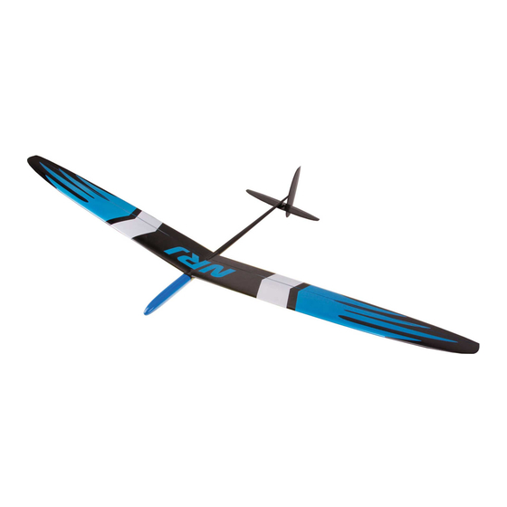
NRJ – Assembly and settings manual
Thank you for the purchase of our glider, we hope that you will enjoy flying it!
Please pay close attention to the following assembly instructions, to have the most reliable machine
the NRJ can be.
Servo tray preparation.
The servo tray is 3D printed and requires some fine-tuning to sit perfectly in place in the fuselage. Small thickness
variations in the fuselage are expected, and as such it is necessary to lightly sand the tray for a perfect mating. The tray
should maintain accurate dimensions in the corners and along the length of its contact with the fuselage. It should also
let servo wires through freely. Run multiple dry fittings and check that the external nose cone slides without forcing or
deformation. An improper placement of the tray may prevent the nose cone from fitting when the servos and servo
horns are mounted.
Advertisement

Related Manuals for OA Composites NRJ

Summary of Contents for OA Composites NRJ
- Page 1 NRJ – Assembly and settings manual Thank you for the purchase of our glider, we hope that you will enjoy flying it! Please pay close attention to the following assembly instructions, to have the most reliable machine the NRJ can be.
- Page 2 To leave the possibility of ballasting the glider correctly, a distance of around 23 mm between the end of the tray and the central lip of the fuselage opening is necessary.
- Page 3 The tray can be glued with fast (less than 90 minutes) epoxy, whose different properties from the long-curing fuselage epoxy allow an easier removal of the servo tray if required. Glue with 4 mating points on the top and bottom sides of the tray.
- Page 4 Check the neutral position of servos with a servo tester An exemple of servo mounting on the tray Servo mounting: It is imperative to do so only once the tray has been glued in right place. Two screws per servo. Check the screw diameter against the tray’s pre-drilled hole, the plastic is hard and fragile screws may break while screwing in, which would obviously complicate assembly.
- Page 5 The NRJ’s fuselage is very thin and space is thus at a premium, however this is the price of having a significant decrease in drag! Aileron horn installation To minimize the “accessory”...
- Page 6 Aileron linkage installation In order to have as little play and as rigid a control rod as possible, it is preferable to use the elements provided in the kit, such as the plastic sleeves and 1mm control rods or TFLE (Teflon) tubes and 1.2mm rods. Check the hole diameter of the horns both the servo and control horns for a tight fit.
- Page 7 The sleeve must be glued only when the linkage will be entirely cut and ready (elbows and lengths). Don’t forget to insert rod in sleeve first. Immobilize the aileron with a piece of tape and mount the wing on the fuselage. Then prepare the aileron connexion with the right width and shape for an easy mounting/unmounting...
- Page 8 On this photo, the ballast leg on the tray is centered on fuselage line. The new servo trays have this leg brought down a few millimeters… a better ballast connection is now guaranteed. ;-) Glue the sleeves after having slid them with enough linear range near the aileron horn for full flap extension. Their lengths can be adjusted by cutting even if the extremities of the linkage are done.
- Page 9 Tail feathers installation Kinematic requirements: Elevator The necessary servo-side control range is +/- 4mm. Choose a short servo horn for this servo, which will yield higher precision for the elevator’s motion. (In the same way as ailerons...) This will then yield a very high precision of the elevator trim.
- Page 10 Stab pod preparation. The stab pod’s rear is sanded and prepared in our factory to let the elevator wire through. But the final slot must be finished with a 2mm bit drilling and a little file. Pay attention, the slot mustn’t be extended in the boom structure, to ensure the boom stiffness in launch constraints.
- Page 11 Glue the rudder with slow-curing epoxy to have time to double check that it is installed perfectly square. AN OTHER WAY is to use CA but then be sure to drill 3 tiny holes on each side of the boom fitting cover of the fin, allowing the glue (medium CA preferably) to fill the space deeply and correctly.
- Page 12 If using braided steel wire: Be attentive to forcefully bend the loop exactly where needed, with square angles to avoid the wire’s springiness introducing slop in the control, leading to a loss of precision during launch and preset mode. Use the providen steel sleeves to crimp the loops.
- Page 13 DON’T make a simple knot directly attached to the carbon sharpen horn. Make a little hook in a 0.3mm rod. In the case of a fishing braid use, you can make a small hook with a 0.3mm rod, to attach the wire in a permanent fashion on it.
- Page 14 Use a drop of CA to attach the other end of the wire to a long thin control rod that you’ll then slide in through the fuselage up to the front. Hook up the line to the servo horn using a small part of 0.5 or 0.8mm control rod, to avoid friction and allow for easy unmounting.
- Page 15 Once the wires are taut and the knots or sleeves locked in place, take away the tape on the control surface and the spring should take out the 2mm slop built in when taping down the control surface). In general, your control surface should now be perfectly neutral.
- Page 16 Peg installation and wing balancing Do not forget to properly set the tilt angle of the peg, it balances the load transmitted to the ship during launch by the index and middle fingers. This tilt is different for every pilot, due to individual differences in length of the fingers. Make sure to base yourself on the joint position of the last phalanges! A good general indication is somewhere between 5 and 7 degrees.
- Page 17 Balancing the wing is quite necessary, because the peg is very often way too heavy. As a result, the glider may tend to lean towards the peg side, misleading small thermal detection and inducing aileron or rudder trims during launch or flight, which is undesirable.
- Page 18 100gr ballast is quite ok for 8m/s FAI limits conditions with the NRJ, especially if you use the Superstrong, which brings the total weight to 330gr. Gap sealing hinges of the control surfaces In order to minimize drag as much as possible, it is advised to gap seal the hinges of all control surfaces.
- Page 19 Some advices about the flight performance: The NRJ has special gliding characteristics, being able to fly really fast with a good drag in flat foil configuration. But while this is really amazing, you might forget about the consequent sink rate of this flight mode. This is only suitable for quick transitions or returns from downwind explorations with high speed.
Need help?
Do you have a question about the NRJ and is the answer not in the manual?
Questions and answers