Advertisement
Quick Links
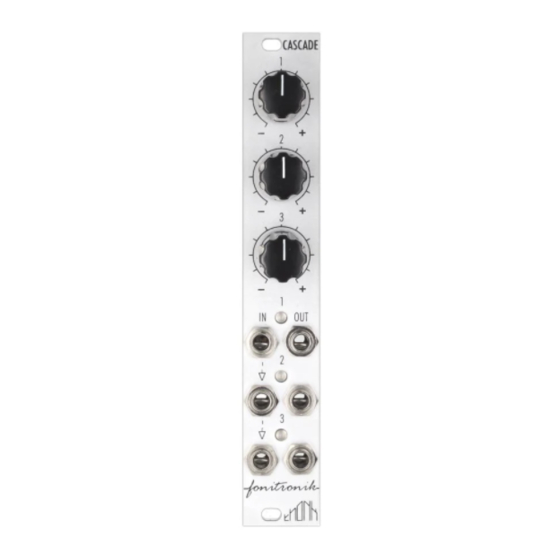
Fonitronik Cascade
Module
FONITRONIK
CASCADE OVERVIEW
For the most recent version of
this document please visit
http://bit.ly/1oZAmev
For all technical support please
visit
http://bit.ly/1u5lua5
on Muffwiggler.
All
Thonk kits are sold under our standard Terms and Conditions -
http://www.thonk.co.uk/faq/
DIY INSTRUCTIONS
This document gives detailed instructions that assume you have purchased a
complete kit from www.thonk.co.uk. It also assumes no previous knowledge
of electronics. To learn to solder try
Adafruit guide to excellent soldering –
Watch and understand that whole YouTube video! If you're not achieving the
results shown in the video then you need to buy new tools or seek advice.
You will not end up with a working module otherwise.
TOOLS REQUIRED
Soldering iron, tweezers for SMD parts, snipe nose pliers, wire strippers,
small flat head screwdriver and diagonal cutters AKA snips AKA side-
cutters. A Digital Multimeter is always helpful for checking for bad solder
joints and continuity. Thonk sell a range of inexpensive tools here -
http://bit.ly/1jxqF3n
November 18
th
2014
www.thonk.co.uk
Eurorack DIY Kit
Instructions
http://youtu.be/I_NU2ruzyc4
http://bit.ly/1l77tF4
Version 1.0
and the
1
Advertisement

Summary of Contents for Fonitronik CASCADE
- Page 1 Fonitronik Cascade Eurorack DIY Kit Version 1.0 Module Instructions FONITRONIK CASCADE OVERVIEW For the most recent version of this document please visit http://bit.ly/1oZAmev For all technical support please visit http://bit.ly/1u5lua5 on Muffwiggler. Thonk kits are sold under our standard Terms and Conditions - http://www.thonk.co.uk/faq/...
-
Page 2: Solder Joints
Fonitronik Cascade Eurorack DIY Kit Version 1.0 Module Instructions SOLDER JOINTS Your solder joints should look like those shown as ‘OK’ below, they should have that neat conical shape on BOTH sides of the PCB. If they don’t look the same on both sides then stop! Work out why from the soldering guides linked and don’t continue until you are getting those results. - Page 3 VCA BUILD INSTRUCTIONS Start by emptying the whole of the Cascade bag A into a bowl or container. This makes it much easier to pick parts as you need them and you’re a lot less likely to lose anything.
- Page 4 Fonitronik Cascade Eurorack DIY Kit Version 1.0 Module Instructions Next solder the four 1K Resistors into positions R6, R12, R18, R19 as shown. Next solder the three 4.7K Resistors into positions R22, R24, R26 as shown. Next solder the three 20K Resistors into positions R5, R11, R17 as shown.
- Page 5 Fonitronik Cascade Eurorack DIY Kit Version 1.0 Module Instructions Next solder the single 5.1V Zener Diode into position Z1 as shown. NOTE! Orientation is vital. The Black ring on the diode should be furthest from the Z1 text.
- Page 6 Fonitronik Cascade Eurorack DIY Kit Version 1.0 Module Instructions Next solder the ten orange 10n capacitors into positions C5, C6, C7, C8, C9, C10, C11, C12, C13 & C14 Next take the 3 pin male header and solder into position JP1 as shown.
- Page 7 Fonitronik Cascade Eurorack DIY Kit Version 1.0 Module Instructions Next solder the two 10uF Electrolytic Capacitors into positions C1 & C2. NOTE! Orientation is vital. The longer lead on the part should be positioned in the square pad marked with the plus/positive symbol.
- Page 8 Fonitronik Cascade Eurorack DIY Kit Version 1.0 Module Instructions Next take the five TL072 ICs out of the protective ESD packaging and position with the circle on the top face at the same end as the notch in the socket NOTE THIS IMAGE IS ROTATED 180 DEGREES silkscreen.
- Page 9 Instructions Start by emptying the whole of the Cascade bag B into a bowl or container. This makes it much easier to pick parts as you need them and you’re a lot less likely to lose anything. First you may need to modify the...
- Page 10 Fonitronik Cascade Eurorack DIY Kit Version 1.0 Module Instructions Next remove the panel and put the LEDs into the PCB with the longer lead going into the hole marked with a + sign but NOT SOLDER yet. Carefully place the panel into position and...
- Page 11 The red stripe should be on the side of the PCB closest to the female header and furthest from the diode. You are now ready to power up & read the instruction manual from Fonitronik here: http://bit.ly/1oZ5muZ And if you have any build problems please direct them to the Muffwiggler forum here: http://bit.ly/1u5lua5...
Need help?
Do you have a question about the CASCADE and is the answer not in the manual?
Questions and answers