Advertisement
Quick Links
Advertisement

Summary of Contents for BBB MICRO System
- Page 1 MICRO System User Manual Version: V1.0 Release date: 2020.08 TBB Power Ltd.
- Page 2 1. System compoments............................3 2. Wiring diagram ..............................4 3. Panels and pairing operation ..........................5 3.1 Wireless switch panel WMSP4......................5 3.2 LED control panel CCP3 ........................6 3.3 Pair WMSP4 with load module CRS17 ..................6 4. Smart battery charger operation and setting 4.1 Front panel of smart battery charger BS1210 ..................
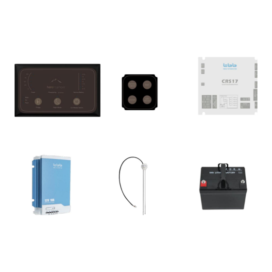
- Page 3 CCP3 WMSP4 CRS17 BS1210 M12-30-S Table 1 Component list of MICRO system Component Descrption Unit CCP3 LED control panel WMSP4 Wireless switch panel with 4 buttons CRS17 Load module with 7 outputs BS1210 Smart battery charger, 12V10A output Capacitive water tank sensor...
- Page 4 Figure 1 System diagram of MICRO system...
- Page 5 Before using WMSP4 please confirm the dip switch is correct. The position of dip switch is shown as below picture Figure 2 The right dip switch setting of WMSP4 Remarks: There has to be 2pcs CR2032 cell battery to power WMSP4 (See below Picture) 2pcs CR2032 cell battery Figure 3 Two pieces cell batteries are required to power WMSP4...
- Page 6 Figure 4 LED control panel CCP3 Table 2 Function description of CCP3 Lableing Type Description Fridge ON/OFF control Power ON/OFF fridge All the indicator of CCP3 will be turned OFF Night Mode Scene Mode except “Night Mode” 12V Master Switch DC load control To turn ON/OFF all DC loads Water Tank...
- Page 7 Figure 5 Front panel of BS1210 Table 3 Descripton of front panel BS1210 Description Remarks Three status: - Blue for battery type LED1 - Green for charging stages - Flashing for faulty LED2 LED3 LED4 LED5 LED of charging status LED of battery type Main button Short press main button, the LED 1 will be cycle display as Blue, Green and Red flashing:...
- Page 8 ➢ Green: Display charging stages. LED2 to LED4 represents charging stages of Bulk, Absorption and Float ➢ Red flashing: Faulty of charging When LED1 stays at Blue, long press main button for 5 seconds to enter into battery type setting; and then short press main button to select battery type as: ➢...
- Page 9 Table 4 Specification of load module CRS17 Electrical Specifications (CRS 17) Input voltage 10.5~16V Numbers Nominal Charging Charger channel current Max charging current Numbers Relay Rated current Fused Outputs Numbers lights Rated current Numbers LED Dimmable Rated current Disconnect 10.5V Battery Delay off time 5mins<10.5V...
- Page 10 Table 5 Specification of smart battery charger BS1210...
- Page 11 Figure 6 Dimension of CRS17 (Unit: mm) To BS1210 To Battery To DC Outputs Figure 7 Connectors of CRS17...
- Page 12 To CCP3 To RSE Figure 8 Connectors of CRS17 Figure 9 Dimension of CCP3 (Unit: mm)
- Page 13 Figure 10 Dimension of WMSP4 (Unit: mm) Figure 11 Dimension of BS1210 (Unit: mm)
- Page 14 Kronings Aps Web: www.kronings.com Tel: +4570 225 840 Email: service@kronings.com...
Need help?
Do you have a question about the MICRO System and is the answer not in the manual?
Questions and answers