Table of Contents
Advertisement
Advertisement
Table of Contents

Subscribe to Our Youtube Channel
Summary of Contents for Easee Base
- Page 1 Installation guide Easee Base...
- Page 2 IMPORTANT Read carefully before use. Keep for future reference. You can find other languages available on our website: easee.support...
-
Page 3: Table Of Contents
Table of Introduction Technical specifications contents Safety instructions Common parts Adapter plate 1-Way 2-Way 3-Way / 4-Way Power Rail Before connecting Ground connection plate Terminals Wiring Side panel Practical details... -
Page 4: Introduction
Introduction Easee Base The Easee Base is a modular charging post for mounting up to four Easee Charging Robots. With Easee Base, it is possible to choose between four different configurations. One-way setup where only one charger is mounted, 2-way setup with two chargers, 3-way setup with three chargers and finally 4-way setup where there is a charger on all sides of the post. -
Page 5: Technical Specifications
Technical specifications General Dimension (mm): H: 1500 x W: 156 x D: 80 Weight: 6.1–7.7 kg Material: Aluminium Finish: Powder coating Colour: Black IP degree: IP44 Features foundation Adapter plate for c/c 160 mm 45 degree rotation intervals (using the adapter plate) Screws and nuts included Electrical connection Connection via Power Rail... -
Page 6: Safety Instructions
Safety Read the entire manual carefully before installing and operating the product. Observe the following instructions: instructions Safety instructions for — This product shall only be installed, repaired or serviced the installation by an authorised electrician. All applicable local, regional and national regulations for electrical installations must be respected. - Page 7 — It is advisable to have an extra protection around the post when mounted in an open parking space. — This product is not intended for use by persons with reduced physical, mental or sensory capabilities (including children) or persons without knowledge of the product. —...
-
Page 8: Common Parts
Common parts Column Side panel Power Rail Adapter plate Ground connection plate Screws, washers and nut... -
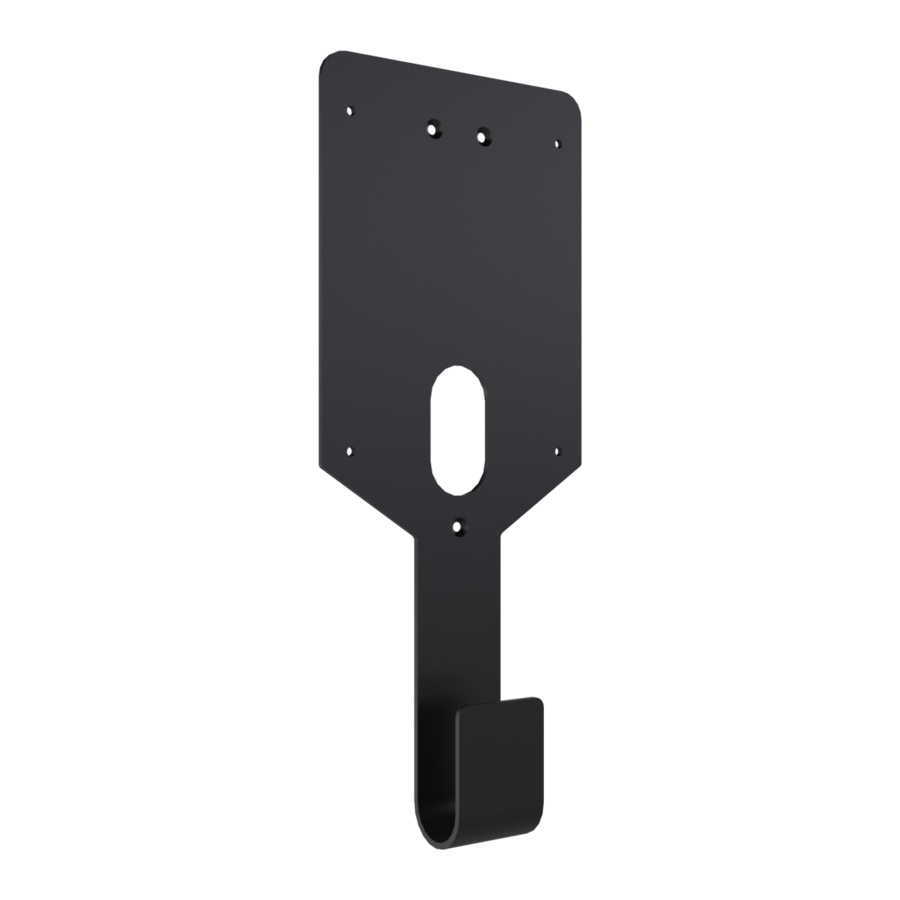
Page 9: Adapter Plate
Common parts Attach the foundation of the column to the adapter plate Adapter plate with 4 socket head screws. Recommended torque is 30-40 Nm. INFO! It can be mounted in 45° increments to get the correct direction. Column at a 45° angle... -
Page 10: 1-Way
1-Way... - Page 11 1-Way Parts Mounting plate 1-way blind cover Screws...
- Page 12 1-Way Attach mounting plate and blind cover to the column with Plate and 3 flat head screws each (6 screws total). cover NOTICE! Make sure the top end of the column is sealed with a plastic cap.
- Page 13 1-Way Thread the cable through the hole in the column and Backplate the Easee charger backplate before attaching it with 4 rounded head screws.
-
Page 14: 2-Way
2-Way... - Page 15 2-Way Parts Mounting plates Screws...
- Page 16 2-Way Attach the mounting plates to the column with 3 flat head Plates screws each (6 screws total). NOTICE! Make sure the top end of the column is sealed with a plastic cap.
- Page 17 2-Way Thread the cables through each hole in the column and the Backplates Easee chargers backplates before attaching them with 4 rounded head screws (8 screws total).
-
Page 18: 3-Way / 4-Way
3-Way / 4-Way... - Page 19 3-Way / 4-Way Parts Top plate Top frame Bottom frame 3-way blind cover Screws...
- Page 20 3-Way / 4-Way Slide the bottom frame over the column and fasten it to the Bottom frame lower threaded hole with 1 flat head screw on each side (2 screws total).
- Page 21 3-Way / 4-Way Attach the top frame to the top two threads using Top frame 2 flat head screws on each side of the column (4 screws in total).
- Page 22 3-Way / 4-Way Cover the top frame with the top plate and fix it with Top plate 4 rounded head screws. NOTICE! Make sure that all cables are pulled through the column holes (2 on each side) before attaching the chargers backplates.
- Page 23 3-Way / 4-Way Now attach the first 2 Easee chargers backplates to the First sides perpendicular to the column openings with 4 rounded head screws each (8 screws total). 2 chargers NOTICE! Pull the cable through the hole in the backplates...
- Page 24 3-Way If you are installing a 3-way setup, attach the last backplate Last charger to one of the open sides and close the other one with the blind cover. and cover Before attaching the blind cover, the shielding tab must be flipped up in order to mount the blind cover plate with 4 rounded head screws.
- Page 25 4-Way If you are installing a 4-way setup, attach the last 2 Easee Last chargers backplates to the column with 4 rounded head screws each (8 screws total). 2 chargers NOTICE! Before installing the electronics in the backplates, they must all be programmed - please check the installation guide that came with the Charging Robots.
-
Page 26: Power Rail
Power Rail... -
Page 27: Before Connecting
Power Rail The Power Rail is a connection box that allows multiple Before charging posts to be connected in series. connecting Please pay attention to the earthing system of the charging post, which is described carefully in the following pages. WARNING! The Power Rail is a product to be installed by an authorized electrician, and a declaration of conformity... -
Page 28: Ground Connection Plate
Power Rail Before installing the Power Rail make sure to apply Ground the ground connection plate. The plate is essential for connecting the post to the protective earth (PE). connection plate Make sure the top PE terminal screw is open, then wedge the end of the plate into the terminal from the back. - Page 29 Insert the serrated washer on the rod inside the column. It should be placed between the metal column and the Power Rail. Slide the Power Rail with the ground connection plate inside the column and latch the bottom of the rail into the catch.
- Page 30 Fasten the grounding nut with the spring washer on the rod. NOTICE! In order to complete the PE connection, the grounding nut has to be fastened and the top PE terminal screw has to be tightened (regardless of whether there is a wire in it or not).
-
Page 31: Terminals
Power Rail The ground connection plate connects the entire leftmost lane Terminals to the metal column, so it is very important that this lane is only used for PE connections. We recommend using the two lower terminal sets for the main power cables. - Page 32 We recommend using the two upper terminal sets for the charger cables. For a single charger, only one set of terminals is used, for two chargers, both sets of terminals are used, and for three or four chargers, two wires have to share a terminal. Wire size up to 6mm².
-
Page 33: Wiring
Power Rail The Power Rail has 5 lanes. This allows support for TN, IT and Wiring TT three and one phase electrical grids. Strip the cable cores by 12 mm. If the cable has flexible conductors, it is recommended to use cable end sleeves on all wires. - Page 34 Wiring TN is the most common grid type in Europe. It uses five TN network conductors to provide both 230 V and 400 V. This makes it very efficient and therefore the preferred grid type for charging electric vehicles. NOTICE! Depending on the time of installation and national standards, the colours of the cables can vary from the illustration below.
- Page 35 Wiring IT and TT grid systems are mostly used in Norway and IT/TT network Albania, but it can also be found in Belgium, France and Spain. These systems have no neutral connector and use only 4 conductors. Therefore they can only provide 230 V (across the phases).
-
Page 36: Side Panel
Power Rail After connecting all wires to the Power Rail, it is time to Side panel mount the side panel with the 4 rounded head screws. -
Page 37: Practical Details
160 mm foundations. We recommend foundations similar to Ørstafundament. In some situations, it is also possible to use the smaller base of the column directly without the adapter plate, in this case using a 80 x 80 center to center footprint. - Page 38 Easee AS. Easee and all other Easee product names and slogans are trademarks or registered trademarks of Easee AS. Easee products can be protected by one or more patents. All other products and services mentioned may be trademarks or service marks of their respective owners.
- Page 40 Easee AS Professor Olav Hanssens vei 7A 4021 Stavanger, Norway .easee-international.com...
Need help?
Do you have a question about the Base and is the answer not in the manual?
Questions and answers