Sign In
Upload
Download
Table of Contents
Contents
Add to my manuals
Delete from my manuals
Share
URL of this page:
HTML Link:
Bookmark this page
Add
Manual will be automatically added to "My Manuals"
Print this page
×
Bookmark added
×
Added to my manuals
Manuals
Brands
Additel Manuals
Furnace
ADT875
User manual
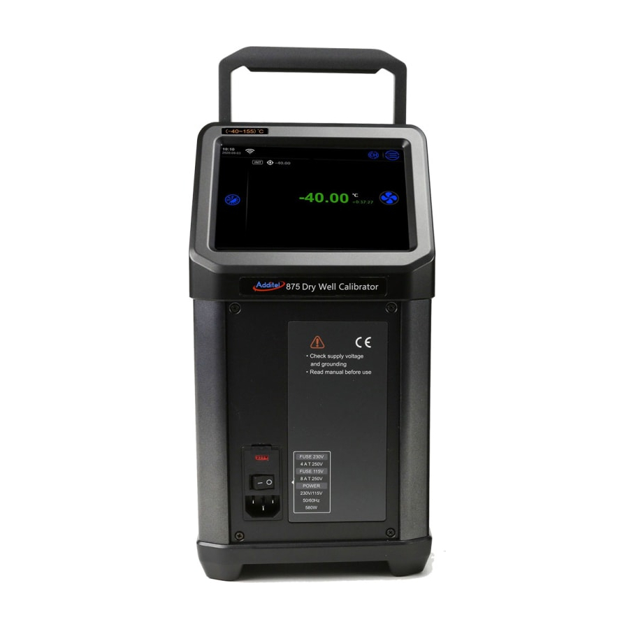
Additel ADT875 User Manual
Thermocouple calibration furnaces
Hide thumbs
1
2
3
Table Of Contents
4
5
6
7
8
9
10
11
12
13
14
15
16
17
18
19
20
21
22
23
24
25
26
27
28
29
30
31
32
33
34
35
36
37
38
39
40
41
42
43
44
45
46
47
48
49
50
51
52
53
54
55
56
57
58
59
60
61
62
63
64
65
66
67
68
69
70
71
72
73
74
75
76
77
78
79
80
81
82
83
84
85
86
87
88
89
90
91
92
93
94
95
96
97
98
99
100
101
102
103
104
105
106
107
108
109
110
111
112
113
114
115
116
117
118
119
page
of
119
Go
/
119
Contents
Table of Contents
Bookmarks
Table of Contents
Table of Contents
Safety Instructions
1 Introduction
Overview
Model Information
Basic Structure
Features
Environmental Conditions
Technical Specifications
General Specifications
Furnace Specifications
Electrical Measurement Specifications
Security Features
Standard Packaging
2 Display Operation
Main Operational Interface
System Temperature Unit Settings
Temperature Output
Temperature Output Settings
Target Temperature Input
Start/Pause Temperature Control
Temperature Control Stabilization
DUT Measurement
DUT Settings
Thermal Couple (TC) Measurement
Electric Current(Ma)Measurement
Switch Test
HART Transmitter Measurement
Hart Communicator
HART Connection and Search
HART Communicator Operations
3 Settings
Communication Settings
Ethernet
Wi-Fi
Bluetooth
Cloud Services
Sensor Library
Management Functions
Standard TC
Date Protection
Acloud Services
System Services
System Calibration
Restore Factory Settings
Maintenance
System Updates
Personalization
Temperature Units
Date and Time
Language
Sound
Brightness
Screen Protection
Display
Product Information
Non-Standard Insert Temperature Deviation
4 Task
Device Center
DUT Management
Temperature Transmitters
Temperature Switchs
Liquid-In-Glass and Surface Thermometers
Temperature Controller, Bimetallic Thermometer, Pressure Type Thermometer and Surface Thermometer
Digital Thermometer
Test Center
Test Task Management
Task Settings
Task Performance
DUT and Test Setting Selection
Task Performance
End of Task
Task Report
Task Data Saving
Data Center
Data Viewing
Data Deletion
Data Search
5 Application
Thermal Calculator
Control Temperature Data Record
Drying and Dehumidification
Step Measurement
Switch Testing
Screen Capature
Advertisement
Quick Links
1
System Calibration
Download this manual
ADT875 & 878 Thermocouple Calibration Furnaces
Table of
Contents
Previous
Page
Next
Page
1
2
3
4
5
Advertisement
Table of Contents
Need help?
Do you have a question about the ADT875 and is the answer not in the manual?
Ask a question
Questions and answers
Subscribe to Our Youtube Channel
Related Manuals for Additel ADT875
Furnace Additel ADT878 User Manual
Thermocouple calibration furnaces (119 pages)
This manual is also suitable for:
Adt878
Adt875pc
Adt878pc
Table of Contents
Print
Rename the bookmark
Delete bookmark?
Delete from my manuals?
Login
Sign In
OR
Sign in with Facebook
Sign in with Google
Upload manual
Upload from disk
Upload from URL


Need help?
Do you have a question about the ADT875 and is the answer not in the manual?
Questions and answers