Table of Contents
Advertisement
Quick Links
Advertisement
Table of Contents

Related Manuals for venotec Abyzz A400 IPU


Summary of Contents for venotec Abyzz A400 IPU
- Page 1 Operating Manual A400 IPU...
- Page 2 Deutschland www.venotec.de Any claims against venotec in relation to the products described in this manual shall be handled exclusively as per the guarantee conditions of the manufacturer. The product specifications may deviate from the information in this manual due to technical improvements and innovations.
-
Page 3: Table Of Contents
Table of contents Page Preface Scope of delivery Function descriprion Warnings Proper use and general information Installation of driver Installation of pump Commissioning Run-in phase Description of control elements Operation Maintenance Guarantee Troubleshooting Disposal Technical data Dimensions Materials Spare parts list Flow charts Declaration of conformity... -
Page 4: Preface
Preface Thank you for buying an Abyzz pump! By buying this powerful product, you have acquired a highly efficient, fully variable pump that was developed and manufactured in Germany to meet the most stringent quality and performance requirements. This manual aims to help you to start using the product and to make the required settings. In order to reap the benefits of this product for as long as possible, please read this manual carefully and observe our recommendations. -
Page 5: Scope Of Delivery
Scope of delivery Abyzz A400 pump with 3m or 10m cable Abyzz A400 driver incl. mounted power cord (1.5m) Registration form ... - Page 6 Functional Description The heart of the Abyzz pumps is a sinusoidal three-phase synchronous motor. The efficiency of the engine is over 90%, making it one of the most efficient engines. The integrated bearing rinse offers optimum protection against calcification and ensures low-maintenance operation.
-
Page 7: Warnings
Warnings Always disconnect the mains plug before working on the pump! Attention high voltage: An opening of the electronics (Abyzz driver) is prohibited and only to be carried out by the manufacturer! Never disconnect the motor supply line from the driver during operation! Only connect clearly associated parts with each other! ... - Page 8 Intended use and general instructions The product is suitable for pumping liquids (sea water, fresh water, brackish water, chlorinated water and other non-aggressive liquids) at a temperature of + 2 ° C to + 40 ° C. A list of the parts in contact with the medium to be pumped can be found in the appendix, for non o.a.
-
Page 9: Installation Of Driver
Installation of driver Mounting: The product must not be installed outside. The mounting wall must be dry and protected from splashes of water and damp. A suitable power outlet should be available at an appropriate distance. Please keep a distance from ceilings of at least 20cm. -
Page 10: Installation Of Pump
Electrical connection: The Abyzz driver requires a voltage of 100 ... 240V / 50 ... 60Hz. The connection must be made to a suitable, properly installed earthed socket, which is protected by a circuit breaker in accordance with DIN VDE 0100T739 (residual current circuit breaker). -
Page 11: Commissioning
Installation outside a sump: Look for a suitable place where only a few power losses occur due to angles or bends and cable routing. If possible, always use bends instead of angles and connect the pump as far as possible without mechanical stress in order to avoid vibrations on connection lines, which could lead to leaks in the course of time due to screw connections or adhesions. -
Page 12: Run-In Phase
Run in phase Despite very high precision, minimal manufacturing tolerances can not be avoided in the manufacture of the bearings. This condition may generate noise during the start- up phase of the pump. However, this is normal and does not pose a long-term problem. -
Page 13: Description Of Control Elements
Description of control elements Display: The display informs you about the operating status of the pump. The display goes into a sleep mode after 3 minutes for maximum life and lowest power consumption. Pressing a button turns the display on again. The overview changes every 2 seconds as follows and displays the operating data such as energy use, mode of operation, speed setting etc. - Page 14 - BOOST MODE: When the BOOST MODE is activated, the pump generates a separate interval regardless of the programmed operating state, e.g. to stir up dirt. If you have selected the operating mode, press "Start / Stop". You will then be asked to enter the corresponding data (minimum and maximum power, time interval).
-
Page 16: Maintenance
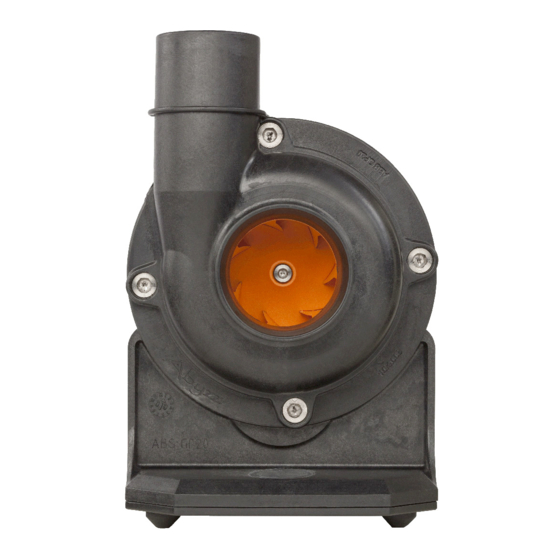
Maintenance Danger - strong magnetic field ! Danger to life for people with pacemakers! Do not bring rotors near pacemakers, credit cards, data carriers or similar items that are sensitive to magnetic fields! Danger of injury due to clamping! Do not place metal parts near the rotor! ... - Page 17 Fig. 1: Pump with pump head (A200)
- Page 18 Fig. 2: Loosening of impeller components (rotor unit) Fig. 3: Disassemly of impeller components (rotor unit)
- Page 19 Fig. 4 a/b: Removed impeller component and close-up of bearing (left) If you need to disassemble the impeller wheel, use a suitable Allen wrench to undo the retaining screw (fig. 5) and pull the impeller wheel off the shaft. This screw is made of titanium and must not be replaced by another screw.
- Page 20 Fig. 5: Disassembly of impeller wheel When assembling the pump (fig. 6 and 7), please make sure that the guide lug (A) fits into the corresponding opening on the magnetic impeller plate and that the flushing opening (C) is in the right place. Make sure that the bearing (B) is in the correct position inside the motor.
- Page 21 Fig. 6: Rear bearing seat, guide lug, and flushing opening O-rings and rubber parts suffer from unavoidable aging and should be replaced as required. These parts are listed in the spare parts list and can be ordered by stating the part number.
- Page 22 Fig. 7: O-ring position and assembly Carefully place the impeller into the motor block and press the assembly into the bearing seat until the bearing bracket is flush with the flange. Screw the pump head back onto the motor block. The screws must be tightened crosswise to create even pressure on the O-ring seal and to ensure impermeability.
-
Page 23: Guarantee
Guarantee In accordance with the implied warranty, we provide a 12-month guarantee. You can also extend the product guarantee period from 12 months to 10 years free of charge within 4 weeks of purchasing the product (date of invoice) after registering your product successfully. - Page 24 Technical changes Due to the constant further development of our products and to innovations that, in particular, serve to improve quality, safety, and technical progress, the manufacturer reserves the right to make technical changes.
-
Page 25: Troubleshooting
Troubleshooting If, despite the high standard of quality, faults should occur, please use the checklist below to rectify or restrict the problem. A number of faults are already detected and displayed by the electronics. Malfunction Cause Remedy The display does not a) Screensaver on a) Press a button light up and the LED... -
Page 26: Disposal
Disposal As per Directive 2002/96/EC, this product cannot be disposed of in normal household rubbish. Within Germany, our customers can send old devices back to us free of charge for proper recycling or disposal. The WEEE number for reporting to the EAR (Germany registry of old electrical equipment) is: DE 16546900 If you do not want to dispose of the product through us, you must bear the costs of... - Page 27 Technische Daten Model Abyzz A400 Maximum flow rate 23.500 l/h Rated flow rate 18.600 l/h Discharge flow speed maximum : 7,5 m/s rated 6,4 m/s Delivery height maximum : 12,5 m Rated input 4...400 W Operating voltage 230V~, 50…60Hz For details, see the characteristic curves in the appendix (fig. 10 et seq.). The following calibrated devices were used for the measurement process: Power test Zimmer LMG 310...
-
Page 28: Dimensions
Dimensions and weight Dimensions in millimeter! Fig. 8: Dimensions pump A400... -
Page 29: Materials
Materials The following components/substances come into contact with the medium being conveyed: Housing Pump head Impeller wheel : ABS GF 20, PA-6 Flushing line : PVC, PU Shaft : WCNi Impeller : Titanium grade 2 Screws : Titanium grade 2 Bearings : SSIC O-ring... - Page 30 Ersatzteilliste Fig. 9: Exploded drawing (top) Fig. 10: Screw and Nut (A200, right) Screw M6x16/Ti(4x) Pump head Impeller wheel Bearing bracket Pump head O-ring Bearing bracket O-ring (large) Bearing bracket O-ring (small) Bearing seat O-ring (2x) Bearing (2x) Compression bearing rubber seal Compression bearing Rotor Motor block (3m)
-
Page 31: Flow Charts
FIg. 11: Flow charts... -
Page 32: Declaration Of Conformity
CE declaration of conformity venotec GmbH Am Nordkreuz 36 26180 Rastede We hereby declare that the design of the pump system Abyzz A400 IPU The following relevant provisions: EC Directive 2004/108/EU Applied harmonized standards: DIN EN 61000-6-1 DIN EN 61000-6-2... - Page 33 WWW.ABYZZ.DE...