Advertisement
Quick Links
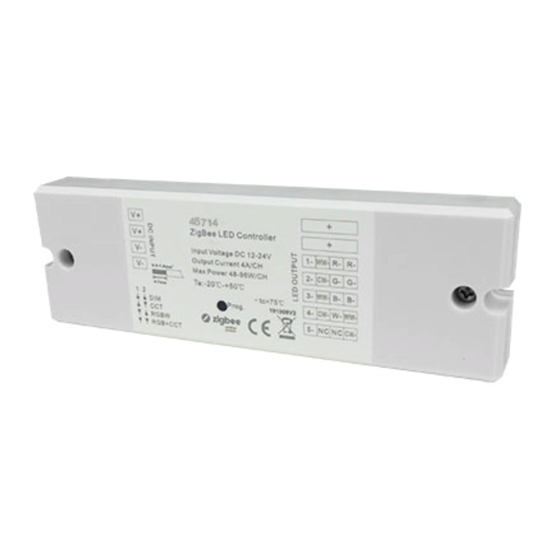
CONTROLEUR ZIGNEE 4 in 1
CODE : 45714
4 in 1 Universal ZigBee LED Controller
AVERTISSEMENT : L'installation doit être réalisée par des personnes qualifiées en respectant les normes et réglementations en vigueur. Il est rappelé que la décision d'installation des produits dans un environnement compatible et conforme aux normes et règles de l'art, est de la responsabilité pleine
FR
et entière de l'acheteur et de l'installateur. Lisez et respectez les instructions avant d'installer, de mettre sous tension ou d'utiliser les produits. Nous déclinons toute responsabilité résultant d'une mise en œuvre ou d'une installation inappropriée des produits.
Les appareils ne doivent pas être modifiés, même partiellement, faute de quoi la garantie ne pourra s'appliquer.
al ZigBee LED Controller
IMPORTANT : Toujours couper le courant au niveau du réseau avant chaque opération d'installation ou de maintenance.
Important: Read All Instructions Prior to Installation
Function introduction
Entrée
Indicateur LED : reste fixe lorsque le
LED indicator, stays solid on when power on the controller, turns
12-24VDC Power input
off after added to a zigbee hub, indicates (same status as connected
12 - 24 VDC
contrôleur est sous tension
load) when program the controller (network pairing, touchlink, factory reset)
nstructions Prior to Installation
n
ZigBee LED Controller
LED indicator, stays solid on when power on the controller, turns
Input Voltage DC 12-24V
1-
WW-
R- R-
off after added to a zigbee hub, indicates (same status as connected
Output Current 4A/CH
2-
CW-
G- G-
Max Power 48-96W/CH
load) when program the controller (network pairing, touchlink, factory reset)
Ta:-20℃-+50℃
3-
WW-
B- B-
1 2
Prog.
4-
CW-
W-
DIM
ON
CCT
5-
NC
NC
RGBW
1 2
RGB+CCT
ZigBee LED Controller
Touche programme :
Switch pour la sélection des 4
Program Key:
Dial switch for device mode
press and hold down to increase/decrease light intensity
selection, DIM, CCT, RGBW
appui court pour allumer / éteindre l'appareil
modes : DIM, CCT, RGBW et
Input Voltage DC 12-24V
and RGB+CCT 4 modes are available,
1-
WW-
R- R-
Maintenir enfoncé pour augmenter / diminuer
RGB + CCT. Le mode par défaut
Output Current 4A/CH
factory default is RGB+CCT mode
2-
CW-
G- G-
l'intensité lumineuse
Max Power 48-96W/CH
est le mode RGB + CCT
1) Under RGBW mode, W channel can only be turned on through color temperature control command (RGBW
Ta:-20℃-+50℃
will be identified as RGB+CCT by zigbee). Color temperature control will mix RGB channels as 1 channel white
3-
WW-
B- B-
and then make color tuning with the 4th channel white. Once turned on, the brightness of white channel will be
4-
CW-
W-
WW-
Prog.
M
controlled together with RGB channels.
1.
En mode RGBW, le canal W ne peut être activé que via la commande de contrôle de la
T
5-
NC
NC
CW-
BW
2) Under RGB+CCT mode, RGB channels and tunable white channels are controlled separately, they can not
température de couleur (RGBW sera identifié comme RGB + CCT par le zigbee). Le contrôle
B+CCT
be turned on and controlled at the same time.
de la température de couleur mélangera les canaux RGB en un canal blanc. Effectuez ensuite
Product Data
le réglage des couleurs avec le 4ème canal blanc. Une fois allumé, la luminosité du canal blanc
sera contrôlé avec des canaux RGB.
short press to switch on/off the device,
Program Key:
e
Input
Output
Output
Remarks
Size(LxWxH)
Voltage
Current
Power
press and hold down to increase/decrease light intensity
W
e available,
2.
12-24VDC
4A/CH
48-96W/CH
Constant voltage
145x46.5x16mm
En mode RGB + CCT, les canaux RVB et les canaux blancs réglables sont contrôlés séparé-
T mode
ment : ils ne peuvent pas être allumés et contrôlés en même temps.
• 4 in 1 universal Zigbee LED controller based on latest ZigBee 3.0 protocol
channel can only be turned on through color temperature control command (RGBW
• 4 different device modes DIM, CCT, RGBW and RGB+CCT in 1 controller, and selectable by dial switch
CCT by zigbee). Color temperature control will mix RGB channels as 1 channel white
• Enables to control ON/OFF, light intensity, color temperature, RGB color of connected LED lights
ng with the 4th channel white. Once turned on, the brightness of white channel will be
1. SPÉCIFICATIONS TECHNIQUES
RGB channels.
• Can directly pair to a compatible ZigBee remote via Touchlink
• Supports self-forming zigbee network without coordinator
e, RGB channels and tunable white channels are controlled separately, they can not
• Supports find and bind mode to bind a ZigBee remote
ed at the same time.
Caractéristiques électrique
• Supports zigbee green power and can bind max. 20 zigbee green power remotes
d'entrée
• Compatible with universal Zigbee gateway or hub products
Output
• Compatible with universal Zigbee remotes
Ambient
outpout current
Remarks
Size(LxWxH)
Temperature
Power
• Waterproof grade: IP20
48-96W/CH
Constant voltage
Courant de sortie
145x46.5x16mm
-20℃ ~ +50℃
Safety & Warnings
• DO NOT install with power applied to device.
ED controller based on latest ZigBee 3.0 protocol
Remarque
Courant constant
• DO NOT operate the dial switches for device mode selection with power applied to device.
• DO NOT expose the device to moisture.
s DIM, CCT, RGBW and RGB+CCT in 1 controller, and selectable by dial switch
dimensions
145x46.5x16mm
OFF, light intensity, color temperature, RGB color of connected LED lights
Température de fonctionnement
mpatible ZigBee remote via Touchlink
Température max du boitier
gbee network without coordinator
mode to bind a ZigBee remote
Dimensions
145x46.5x16mm(L*l*H)
power and can bind max. 20 zigbee green power remotes
Le contrôleur LED Zigbee universel 4 in 1 est basé sur le dernier protocole ZigBee 3.0.
al Zigbee gateway or hub products
- 4 modes d'appareil différents : DIM, CCT, RGBW et RGB + CCT dans le contrôleur, sélection-
al Zigbee remotes
nable par commutateur à cadran.
- Permet le contrôle ON / OFF, l'intensité lumineuse, la température de couleur, la couleur RGB
des produits LED connectés.
- Peut se coupler directement à une télécommande ZigBee compatible.
- Possibilité de lier 20 télécommandes ZIGBEE maximum.
er applied to device.
- Compatible avec des produits ou hub Zigbee universels
l switches for device mode selection with power applied to device.
- Protection IP20
ice to moisture.
Operation
ZG.01029.04737
1.Do wiring according to connection diagram correctly, please power off and power on the device once
a device mode is selected so that the selected mode can be activated.
Operation
ZG.01029.04737
2.This ZigBee device is a wireless receiver that communicates with a variety of ZigBee compatible
1.Do wiring according to connection diagram correctly, please power off and power on the device once
systems. This receiver receives and is controlled by wireless radio signals from the compatible ZigBee
a device mode is selected so that the selected mode can be activated.
system.
2. FONCTIONNEMENT
3. Zigbee Network Pairing through Coordinator or Hub (Added to a Zigbee Network)
2.This ZigBee device is a wireless receiver that communicates with a variety of ZigBee compatible
1.
Effectuez le câblage conformément au schéma, veuillez éteindre et allumer l'appareil une fois que le
Step 1: Remove the device from previous zigbee network if it has already been added to, otherwise pairing will
systems. This receiver receives and is controlled by wireless radio signals from the compatible ZigBee
mode est sélectionné afin que le celui-ci puisse être activé.
fail. Please refer to the part "Factory Reset Manually".
system.
sortie +
Common Anode Output(+)
Step 2: From your ZigBee Controller or hub interface, choose to add lighting device and enter Pairing mode as
2.
Cet appareil ZigBee est un récepteur sans fil qui communique avec une variété de systèmes com-
instructed by the controller.
CH1:R/R/WW/1 output(-)
CH1 : R/Rouge/WW sortie -
patibles ZigBee. Ce récepteur reçoit et est contrôlé par des signaux radio sans fil ZigBee compatibles.
3. Zigbee Network Pairing through Coordinator or Hub (Added to a Zigbee Network)
CH2 : Green/Vert/CW sortie -
CH2:G/G/CW/2 output(-)
Step 3: Re-power on the device to set it into network pairing mode (connected light flashes twice slowly),
CH3 : Blue/Bleu/WW sortie -
CH3:B/B/WW/3 output(-)
network pairing mode lasts 15S (enters into touchlink mode after 15S), once timeout, repeat this step.
3.
Step 1: Remove the device from previous zigbee network if it has already been added to, otherwise pairing will
Couplage du réseau Zigbee via le coordinateur ou le hub (ajouté à un réseau Zigbee)
CH4:WW/W/CW/4 output(-)
CH4 : WW/W/CW sortie -
WW-
CH5:CW/NC/NC/5 output(-)
fail. Please refer to the part "Factory Reset Manually".
CH5 : CW sortie -
CW-
Étape 1 : supprimez l'appareil du réseau zigbee précédent s'il a déjà été ajouté, sinon le jumelage
NC = No Connection
échouera. Veuillez vous référer à la partie "Réinitialisation manuelle de l'usine" ci-dessous.
Common Anode Output(+)
Step 2: From your ZigBee Controller or hub interface, choose to add lighting device and enter Pairing mode as
short press to switch on/off the device,
Étape 2 : À partir de votre contrôleur ZigBee ou de votre hub, choisissez d'ajouter un dispositif
instructed by the controller.
d'éclairage et entrez en mode de couplage comme indiqué par le contrôleur.
CH1:R/R/WW/1 output(-)
Étape 3 : Rallumez l'appareil pour le mettre en mode de couplage réseau (le voyant connecté clignote
CH2:G/G/CW/2 output(-)
Step 3: Re-power on the device to set it into network pairing mode (connected light flashes twice slowly),
deux fois lentement), le mode de couplage réseau dure 15 secondes (passage en mode lien tactile
5. Removed from a Zigbee Network through Coordinator or Hub Interface
CH3:B/B/WW/3 output(-)
network pairing mode lasts 15S (enters into touchlink mode after 15S), once timeout, repeat this step.
après 15 secondes), une fois le délai d'expiration écoulé, répétez cette étape.
CH4:WW/W/CW/4 output(-)
Étape 4 : La lumière connectée clignotera 5 fois, puis restera allumée, puis l'appareil apparaîtra dans
CH5:CW/NC/NC/5 output(-)
le menu de votre contrôleur. Il peut être alors contrôlé via l'interface du contrôleur ou du hub.
NC = No Connection
4. TouchLink to a Zigbee Remote
Step 1: Method 1: Short press "Prog" button (or re-power on the device) 4 times to start Touchlink
Ambient
Max. Casing
commissioning (lasts for 180S) immediately under any circumstances, once time out, repeat this step.
Temperature
Temperature
Method 2: Re-power on the device, Touchlink commissioning will start after 15S if it's not added to a zigbee
-20℃ ~ +50℃
75℃
network, 165S timeout. Or start immediately if it's already added to a network, 180S timeout. Once timeout,
Max. 20A input
repeat the step.
< 10cm
4. TouchLink to a Zigbee Remote
12-24 VDC
Zigbee
Remote
4.
Remise à zéro
Step 1: Method 1: Short press "Prog" button (or re-power on the device) 4 times to start Touchlink
Max. Casing
4A/CH
commissioning (lasts for 180S) immediately under any circumstances, once time out, repeat this step.
Temperature
6. Factory Reset Manually
Étape 1: Appuyez brièvement sur «Prog» 5 fois en continu ou rallumer l'appareil 5 fois de façon
Method 2: Re-power on the device, Touchlink commissioning will start after 15S if it's not added to a zigbee
48-96W/CH
75℃
consécutive si "Prog." n'est pas accessible.
network, 165S timeout. Or start immediately if it's already added to a network, 180S timeout. Once timeout,
Step 1: Short press "Prog." key for 5 times continuously or re-power on the device for 5 times continuously if
Note: 1) Directly TouchLink (both not added to a ZigBee network), each device can link with 1 remote.
2) TouchLink after both added to a ZigBee network, each device can link with max. 30 remotes.
repeat the step.
the "Prog." key is not accessible.
3) For Hue Bridge & Amazon Echo Plus, add remote and device to network first then TouchLink.
4) After TouchLink, the device can be controlled by the linked remotes.
-20°C ~ +50°C
Max. 20A input
75°C
< 10cm
Zigbee
Remote
Note: 1) If the device is already at factory default setting, there is no indication when factory reset again .
Remarque :
1. Si l'appareil est déjà en réglages d'usine par défaut, il n'y a aucune indication lors de la réinitialisa-
Note: 1) Directly TouchLink (both not added to a ZigBee network), each device can link with 1 remote.
tion d'usine.
2) TouchLink after both added to a ZigBee network, each device can link with max. 30 remotes.
2. Tous les paramètres de configuration seront réinitialisés après la réinitialisation ou la suppression
7. Factory Reset through a Zigbee Remote (Touch Reset)
3) For Hue Bridge & Amazon Echo Plus, add remote and device to network first then TouchLink.
de l'appareil du réseau.
4) After TouchLink, the device can be controlled by the linked remotes.
Step 1: Re-power on the device to start TouchLink Commissioning, 180 seconds timeout, repeat this step.
EUROPOLE - 19, avenue ZAC de Chassagne - 69360 TERNAY - Fax : +33 (0)4 72 24 73 42 - www.europole.net
Step 4: Connected light will blink 5
times and then stay solid on, then the
device will appear in your controller's
L
menu and can be controlled through
V+
12V/24V
N
CV PSU
V-
AC Power
G
controller or hub interface.
50/60Hz
Max. 20A input
V+
V+
R-
R-
ZigBee LED Controller
Input Voltage DC 12-24V
1-
WW-
R- R-
G-
G-
Output Current 4A/CH
B-
B-
Max Power 48-96W/CH
2-
CW-
G- G-
Ta:-20℃-+50℃
3-
WW-
B- B-
1 2
DIM
Prog.
4-
CW-
W-
WW-
Step 4: Connected light will blink 5
ON
CCT
5-
NC
NC
CW-
RGBW
V+
V+
1 2
RGB+CCT
WW-
WW-
times and then stay solid on, then the
CW-
CW-
From your ZigBee controller or hub interface, choose to delete or reset
device will appear in your controller's
the lighting device as instructed. The connected light blinks 3 times to
L
V+
menu and can be controlled through
12V/24V
N
indicate successful reset.
CV PSU
V-
AC Power
G
controller or hub interface.
50/60Hz
V+
V+
Step 4: There shall be indication on
R-
R-
ZigBee LED Controller
the remote for successful link and
L
V+
Input Voltage DC 12-24V
12V/24V
1-
WW-
R- R-
N
G-
G-
connected light will flash twice.
Output Current 4A/CH
CV PSU
V-
G
AC Power
Max Power 48-96W/CH
2-
CW-
G- G-
B-
B-
50/60Hz
Ta:-20℃-+50℃
3-
WW-
B- B-
Max. 20A input
5. Removed from a Zigbee Network through Coordinator or Hub Interface
1 2
4-
CW-
W-
WW-
DIM
Prog.
ON
V+
V+
CCT
5-
NC
NC
CW-
R-
R-
RGBW
ZigBee LED Controller
V+
V+
1 2
RGB+CCT
WW-
WW-
Input Voltage DC 12-24V
1-
WW-
R- R-
G-
G-
CW-
CW-
Output Current 4A/CH
2-
CW-
G- G-
B-
B-
Max Power 48-96W/CH
Ta:-20℃-+50℃
3-
WW-
B- B-
1 2
DIM
Prog.
4-
CW-
W-
WW-
ON
From your ZigBee controller or hub interface, choose to delete or reset
CCT
5-
NC
NC
CW-
RGBW
V+
V+
1 2
RGB+CCT
WW-
WW-
the lighting device as instructed. The connected light blinks 3 times to
CW-
CW-
Step 2: Bring the remote or touch panel within 10cm of the lighting device.
indicate successful reset.
Step 3: Set the remote or touch panel into Touchlink commissioning,
please refer to corresponding remote or touch panel manual to learn how .
L
V+
12V/24V
N
L
CV PSU
V+
V-
AC Power
12V/24V
G
N
50/60Hz
CV PSU
V-
AC Power
G
Max. 20A input
50/60Hz
6. Factory Reset Manually
V+
V+
ZigBee LED Controller
R-
R-
ZigBee LED Controller
Step 1: Short press "Prog." key for 5 times continuously or re-power on the device for 5 times continuously if
Input Voltage DC 12-24V
1-
WW-
R- R-
Output Current 4A/CH
2-
CW-
G- G-
Input Voltage DC 12-24V
Max Power 48-96W/CH
1-
WW-
R- R-
G-
G-
the "Prog." key is not accessible.
Output Current 4A/CH
Ta:-20℃-+50℃
3-
WW-
B- B-
2-
CW-
G- G-
B-
B-
Max Power 48-96W/CH
1 2
Prog.
4-
CW-
W-
WW-
Ta:-20℃-+50℃
DIM
3-
WW-
B- B-
ON
CCT
1 2
5-
NC
NC
CW-
RGBW
Prog.
4-
CW-
W-
WW-
DIM
ON
1 2
RGB+CCT
CCT
5-
NC
NC
CW-
RGBW
L
V+
1 2
RGB+CCT
V+
12V/24V
N
Step 2: Bring the remote or touch panel within 10cm of the lighting device.
WW-
CV PSU
V-
AC Power
G
CW-
50/60Hz
Step 3: Set the remote or touch panel into Touchlink commissioning,
Max. 20A input
V+
V+
please refer to corresponding remote or touch panel manual to learn how .
R-
R-
2) All configuration parameters will be reset after the device is reset or removed from the network.
ZigBee LED Controller
Input Voltage DC 12-24V
1-
WW-
R- R-
G-
G-
Output Current 4A/CH
Max Power 48-96W/CH
2-
CW-
G- G-
B-
B-
Ta:-20℃-+50℃
3-
WW-
B- B-
1 2
4-
CW-
W-
WW-
DIM
Prog.
ON
CCT
5-
NC
NC
CW-
RGBW
V+
V+
1 2
RGB+CCT
WW-
WW-
CW-
CW-
Note: 1) If the device is already at factory default setting, there is no indication when factory reset again .
2) All configuration parameters will be reset after the device is reset or removed from the network.
7. Factory Reset through a Zigbee Remote (Touch Reset)
L
V+
12V/24V
N
Step 1: Re-power on the device to start TouchLink Commissioning, 180 seconds timeout, repeat this step.
CV PSU
V-
G
Max. 20A input
L
V+
ZigBee LED Controller
12V/24V
N
CV PSU
V-
G
Input Voltage DC 12-24V
1-
WW-
R- R-
6. Factory Reset Manually
Step 1: Short press "Prog." key for 5 times continuously or re-power on the device for 5 times continuously if
the "Prog." key is not accessible.
V+
V-
Max. 20A input
1 2
ON
1 2
Note: 1) If the device is already at factory default setting, there is no indication when factory reset again .
5.
Réinitialisation d'usine via une télécommande Zigbee (réinitialisation tactile)
2) All configuration parameters will be reset after the device is reset or removed from the network.
Étape 1: Remettez l'appareil sous tension pour démarrer la mise en service : passage en mode
lien tactile après 180 secondes. Répétez l'opération.
7. Factory Reset through a Zigbee Remote (Touch Reset)
Step 1: Re-power on the device to start TouchLink Commissioning, 180 seconds timeout, repeat this step.
< 10cm
Zigbee
Remote
RGB LED Strip
CCT LED Strip
Note: Make sure the device already added to a network, the remote added to the same one or not added to any
network.
Remarque:
Assurez-vous que le périphérique soit déjà ajouté à un réseau, que la télécommande soit
ajoutée au même ou non ajoutée à aucun réseau.
RGB LED Strip
6.
Mode Rechercher et Lier
Étape 1: Appuyez brièvement sur «Prog». 3 fois (ou rallumez l'appareil 3 fois) pour démarrer
CCT LED Strip
8. Find and Bind Mode
le mode ''Rechercher et Lier'' (le voyant connecté clignote lentement) pour trouver et lier, délai
RGB LED Strip
d'expiration de 180 secondes, répétez l'étape.
Step 1: Short press "Prog." button 3 times (Or re-power on the device (initiator node) 3 times) to start Find and Bind
mode (connected light flashes slowly) to find and bind target node, 180 seconds timeout, repeat the step.
CCT LED Strip
Max. 20A input
Step 4: There shall be indication on
Étape 2: Le luminaire
the remote for successful link and
Step 2: Connected light flashes 3
clignote 3 fois pour une
Zigbee
Remote
times for successful reset.
connected light will flash twice.
réinitialisation réussie.
V+
V+
R-
R-
RGB LED Strip
RGB LED Strip
G-
G-
Note: Make sure the device and the remote or touch panel already added to the same Zigbee hub.
B-
B-
9. Learning to a Zigbee Green Power Remote
CCT LED Strip
CCT LED Strip
Step 1: Short press "Prog." button 4 times (Or re-power on the device 4 times) to start Learning mode
Step 2: Connected light flashes 3
V+
V+
Remarque:
(connected light flashes twice), 180 seconds timeout, repeat the step.
WW-
WW-
times for successful reset.
V+
assurez-vous que l'appareil et la télécommande ou l'écran tactile sont déjà ajoutés au
CW-
CW-
WW-
CW-
même hub Zigbee.
RGB LED Strip
Max. 20A input
CCT LED Strip
Zigbee
Green Power
Remote
Step 4: There shall be indication
on the remote and connected
light flashes 3 times for
AC Power
50/60Hz
successful reset.
Step 4: There shall be indication
10. Delete Learning to a Zigbee Green Power Remote
on the remote and connected
V+
V+
Step 1: Short press "Prog." button 3 times (Or re-power on the device 3 times) to start delete Learning mode
RGB LED Strip
R-
R-
light flashes 3 times for
(connected light flashes slowly), 180 seconds timeout, repeat the step.
AC Power
Step 2: Connected light flashes 3
L
times for successful reset.
12V/24V
N
CV PSU
G
AC Power
50/60Hz
V+
V+
RGB LED Strip
R-
R-
ZigBee LED Controller
Input Voltage DC 12-24V
1-
WW-
R- R-
G-
G-
Output Current 4A/CH
2-
CW-
G- G-
B-
B-
Max Power 48-96W/CH
Ta:-20℃-+50℃
3-
WW-
B- B-
CCT LED Strip
DIM
Prog.
4-
CW-
W-
WW-
CCT
5-
NC
NC
CW-
RGBW
V+
V+
RGB+CCT
WW-
WW-
CW-
CW-
Étape 4 : Il doit être indiqué
Step 4: There shall be indication
sur la télécommande. Le
on the remote and connected
voyant connecté clignote 3
L
V+
12V/24V
light flashes 3 times for
N
fois lorsque la réinitialisation
V-
CV PSU
AC Power
G
50/60Hz
est réussie.
successful reset.
Max. 20A input
V+
V+
R-
R-
ZigBee LED Controller
Input Voltage DC 12-24V
1-
WW-
R- R-
G-
G-
Output Current 4A/CH
Max Power 48-96W/CH
2-
CW-
G- G-
B-
B-
Ta:-20℃-+50℃
3-
WW-
B- B-
1 2
4-
CW-
W-
WW-
DIM
Prog.
ON
CCT
5-
NC
NC
CW-
RGBW
V+
V+
1 2
RGB+CCT
WW-
WW-
CW-
CW-
8. Find and Bind Mode
Étape 2 : Approchez la télécommande ou l'écran tactile à moins de 10 cm du
Step 2: Bring the remote or touch panel within 10cm of the lighting device.
contrôleur.
Step 3: Set the remote or touch panel into Touch Reset procedure to reset the
Step 1: Short press "Prog." button 3 times (Or re-power on the device (initiator
Étape 3 : Réglez la télécommande ou l'écran tactile en procédure de
device, please refer to corresponding remote or touch panel manual to learn how .
mode (connected light flashes slowly) to find and bind target node, 180 second
réinitialisation tactile pour réinitialiser l'appareil. Veuillez vous reporter au manuel
correspondant de la télécommande ou de l'écran tactile.
L
V+
12V/24V
N
CV PSU
V-
G
Max. 20A input
ZigBee LED Controller
Input Voltage DC 12-24V
1-
WW-
R- R-
Output Current 4A/CH
2-
CW-
G- G-
Max Power 48-96W/CH
Ta:-20℃-+50℃
3-
WW-
B- B-
1 2
4-
CW-
W-
WW-
DIM
Prog.
ON
CCT
5-
NC
NC
CW-
RGBW
Zigbee
1 2
RGB+CCT
Remote
Step 2: Set the remote or touch panel (target node) into f
to find and bind initiator, please refer to corresponding re
L
V+
12V/24V
N
V-
CV PSU
Step 3: There shall be indication on the remote or touch
AC Power
G
50/60Hz
successfully and can control it then .
V+
V+
Note: Make sure the device and the remote or touch panel already added to th
R-
R-
ZigBee LED Controller
Input Voltage DC 12-24V
9. Learning to a Zigbee Green Power Remote
1-
WW-
R- R-
G-
G-
Output Current 4A/CH
Max Power 48-96W/CH
2-
CW-
G- G-
B-
B-
Ta:-20℃-+50℃
3-
WW-
B- B-
1 2
4-
CW-
W-
WW-
Step 1: Short press "Prog." button 4 times (Or re-power on the device 4 times)
DIM
Prog.
ON
CCT
5-
NC
NC
CW-
RGBW
V+
V+
1 2
RGB+CCT
WW-
WW-
(connected light flashes twice), 180 seconds timeout, repeat the step.
CW-
CW-
Étape 2 : réglez la télécommande ou l'écran tactile en mode recherche et
Step 2: Set the remote or touch panel (target node) into find and bind mode, and enable it
liaison et activez-la pour rechercher et lier. Veuillez vous reporter au manuel de
to find and bind initiator, please refer to corresponding remote or touch panel manual.
la télécommande ou de l'écran tactile correspondant.
Step 3: There shall be indication on the remote or touch panel that it bind the device
Étape 3 : une indication apparait sur la télécommande ou l'écran tactile
L
successfully and can control it then .
V+
informant que l'appareil est lié avec succès et peut ainsi être contrôlé.
12V/24V
N
CV PSU
V-
G
Max. 20A input
ZigBee LED Controller
Input Voltage DC 12-24V
1-
WW-
R- R-
Output Current 4A/CH
Step 3: Connected light will
2-
CW-
G- G-
Max Power 48-96W/CH
flash twice to indicate
Ta:-20℃-+50℃
3-
WW-
B- B-
1 2
Zigbee
L
Prog.
4-
CW-
successful learning. Then the
W-
WW-
DIM
ON
V+
Green Power
12V/24V
CCT
N
5-
NC
NC
CW-
remote can control the device.
RGBW
CV PSU
Remote
V-
1 2
RGB+CCT
AC Power
G
50/60Hz
V+
V+
R-
R-
Step 2: Set the green power
ZigBee LED Controller
Input Voltage DC 12-24V
remote into Learning mode,
1-
WW-
R- R-
G-
G-
Output Current 4A/CH
Max Power 48-96W/CH
2-
CW-
G- G-
B-
B-
please refer to its manual.
Ta:-20℃-+50℃
3-
WW-
B- B-
1 2
DIM
Prog.
4-
CW-
W-
WW-
ON
CCT
5-
NC
NC
CW-
RGBW
V+
V+
1 2
RGB+CCT
WW-
WW-
10. Delete Learning to a Zigbee Green Power Remote
CW-
CW-
Note: Each device can learn to
Step 1: Short press "Prog." button 3 times (Or re-power on the device 3 times)
Step 2: Set the green power
remote into Learning mode,
max. 20 zigbee green power remote.
(connected light flashes slowly), 180 seconds timeout, repeat the step.
please refer to its manual.
L
V+
12V/24V
N
CV PSU
RGB LED Strip
CCT LED Strip
AC Power
50/60Hz
V+
V+
R-
R-
G-
G-
B-
B-
V+
V+
WW-
WW-
CW-
CW-
RGB LED Strip
CCT LED Strip
AC Power
50/60Hz
V+
V+
R-
R-
G-
G-
B-
B-
V+
V+
WW-
WW-
CW-
CW-
RGB LED Strip
Note: Each dev
max. 20 zigbee
CCT LED Strip
1
Advertisement

Related Manuals for EUROPOLE 45714


Summary of Contents for EUROPOLE 45714
- Page 1 Step 1: Short press “Prog.” key for 5 times continuously or re-power on the device for 5 times continuously if the “Prog.” key is not accessible. EUROPOLE - 19, avenue ZAC de Chassagne - 69360 TERNAY - Fax : +33 (0)4 72 24 73 42 - www.europole.net Step 2: Connected light flashes 3 CODE : 45714 times for successful reset.
- Page 2 Note: please make sure the dial switches are at position for RGBW mode as shown in above diagram. EUROPOLE - 19, avenue ZAC de Chassagne - 69360 TERNAY - Fax : +33 (0)4 72 24 73 42 - www.europole.net 3) CCT Mode 12.
- Page 3 Step 1: Short press “Prog.” key for 5 times continuously or re-power on the device for 5 times continuously if the “Prog.” key is not accessible. EUROPOLE - 19, avenue ZAC de Chassagne - 69360 TERNAY - Fax : +33 (0)4 72 24 73 42 - www.europole.net Step 2: Connected light flashes 3 CODE : 45714 times for successful reset.
- Page 4 Note: please make sure the dial switches are at position for RGBW mode as shown in above diagram. EUROPOLE - 19, avenue ZAC de Chassagne - 69360 TERNAY - Fax : +33 (0)4 72 24 73 42 - www.europole.net 3) CCT Mode 12.
Need help?
Do you have a question about the 45714 and is the answer not in the manual?
Questions and answers