
Subscribe to Our Youtube Channel
Related Manuals for NCTE 7000 Series


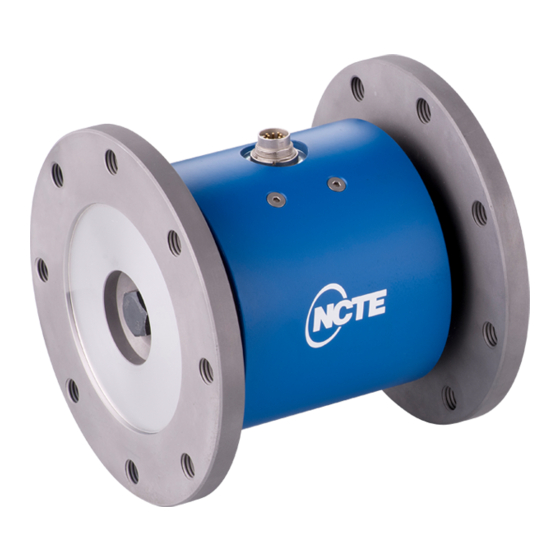
Summary of Contents for NCTE 7000 Series
- Page 1 Instruction manual and data sheet Torque Sensor Series 7000 Version 20/01 – State December 2020...
- Page 2 Copyright © NCTE AG® Torque Sensor Series 7000 Instruction Manual and Data Sheet. This instruction manual is property of NCTE AG®, D-82041 Oberhaching Unauthorized duplication, even in part, is not permitted. State: December 2020...
-
Page 3: Table Of Contents
Instruction manual General ..............................5 Customer service address ........................5 Warranty ............................5 Scope of delivery ..........................5 Safety ................................. 6 Intended use ............................6 Recalibration and duration of use ..................... 6 Structural change..........................6 Training of the operating personnel ....................6 Transport and handling ........................ - Page 4 Technical characteristics .......................... 10 EMV Emission data ..........................11 Dimensions .............................. 12 Additional profile shafts for NCTE flange sensors (accessories) ............. 12 Additional profile sleeve for NCTE flange sensors (accessory) ..............14 Wiring diagram ............................16 10 Sensor wiring ............................16 11 Speed sensor ............................
-
Page 5: Instruction Manual
All information without guarantee subject to technical changes. For further questions, we are of course also available after the purchase at any time. Please use our contact address. 1.1 Customer service address NCTE AG Raiffeisenalle 3 D-82041 Oberhaching Phone: +49 (0)89 665 619 0 Email: sales@ncte.de... -
Page 6: Safety
2.2 Recalibration and duration of use A factory recalibration should be executed annually. See the corresponding label on the sensor. This recalibration can be carried out quickly and easily by NCTE AG. Please contact us. If the sensor is used within the limits of its intended use and regularly calibrated, the sensor's operating life is unlimited. -
Page 7: Torque Sensor Series 7000
The sensor is not designed as a support bearing. The cable length must not exceed 5m. If a cable other than the one supplied by NCTE or an identical cable with a different cable length is used, the function of the sensor system may be impaired. -
Page 8: Starting Up
Check the wiring, connectors and shaft: Every 12 months Repairs and recalibrations can only be carried out by NCTE AG personnel. 3.10 Disposal The device must be returned to NCTE AG, Raiffeisenallee 3, D-82041 Oberhaching for disposal. _______________________________________________________________________________________ Page 8 of 20... -
Page 9: Data Sheet
Note: In case of overload, the sensor leads to a measurement offset. In such case, the sensor needs to be recalibrated at NCTE AG. The sensor should be operated only within the specified nominal torque range. _______________________________________________________________________________________ Page 9 of 20... -
Page 10: Load Characteristics
_______________________________________________________________________________________ Load characteristics Model line Axial force [N] Limit transverse force [N] Limit bending moment [Nm] Series 7000 NCTE 16000 to be avoided to be avoided Customer-specific 16000 to be avoided to be avoided Any irregular stress (bending moment, transverse or axial force, exceeding the nominal torque) up to the specified static load limit is only permissible as long as none of the other stresses can occur. -
Page 11: Emv Emission Data
_______________________________________________________________________________________ Power supply Unit Value Supply voltage 9 … 28 Current consumption (max.) Start-up peak < 100 Absolute max. supply voltage General information Unit Value Protection class according to 50/65 EN 60529 Reference temperature °C +15 … +35 Operational temperature range °C -40 …... -
Page 12: Dimensions
_______________________________________________________________________________________ Dimensions Additional profile shafts for NCTE flange sensors (accessories) Profile shaft 6 teeth (1 3/4''), ≤ 4500 Nm continuous dynamic load _______________________________________________________________________________________ Page 12 of 20... - Page 13 _______________________________________________________________________________________ Profile shaft 6 teeth (1 3/8''), ≤ 2500 Nm continuous dynamic load Profile shaft 20 teeth (1 3/4''), ≤ 5000 Nm continuous dynamic load _______________________________________________________________________________________ Page 13 of 20...
-
Page 14: Additional Profile Sleeve For Ncte Flange Sensors (Accessory)
_______________________________________________________________________________________ Profile shaft 21 teeth (1 3/8''), ≤ 3000 Nm continuous dynamic load Additional profile sleeve for NCTE flange sensors (accessory) Profile sleeve 6 teeth (1 3/4'') ≤ 5000 Nm continuous dynamic load _______________________________________________________________________________________ Page 14 of 20... - Page 15 _______________________________________________________________________________________ Profile sleeve 6 teeth (1 3/8''), ≤ 5000 Nm continuous dynamic load Profile sleeve 20 teeth (1 3/4''), ≤ 5000 Nm continuous dynamic load _______________________________________________________________________________________ Page 15 of 20...
-
Page 16: Wiring Diagram
_______________________________________________________________________________________ Profile sleeve 21 teeth (1 3/8''), ≤ 5000 Nm continuous dynamic load Wiring diagram Binder Plug Series 423/723/425 IP67 Type (Colour coding acc. to DIN 47100) Colour Description Value White CAN / USB H/D- Brown CAN / USB L/D+ Green Angle channel 0V …... -
Page 17: Speed Sensor
_______________________________________________________________________________________ 11 Speed sensor Optical angle sensor with 360 CPR. Parameter Min. Typ. Max. Unit Upper level Output signal Lower level Output signal Parameter Description One cycle (pulse) of 360 CPR Pulse width, or the length of the upper level of the output signal Status width, the length of the electrical degrees between a change from CH. -
Page 18: Order Options
IP 65 7000 5000 Example sensor configuration We would be pleased to provide you with further information about serial products in a personal contact under Phone: +49 (0)89 66 56 19 30 or by e-mail: sales@ncte.de. _______________________________________________________________________________________ Page 18 of 20... -
Page 19: Accessories
8 x M12, 12.9 5.000 You can obtain further or additional accessories and special requests in a personal discussion with your contact person for series products by calling +49 (0)89 66 56 19 30 or by e-mail: sales@ncte.de. _______________________________________________________________________________________ Page 19 of 20... - Page 20 Your experts for magnetostrictive sensors...
Need help?
Do you have a question about the 7000 Series and is the answer not in the manual?
Questions and answers