
Summary of Contents for Chore-Time Turbo-House
- Page 1 Turbo-House Air Inlet Installation & Operator’s Instruction Manual November 2009 MV2308A...
-
Page 2: Chore-Time Warranty
Chore-Time Distributors are not authorized to modify or extend the terms and conditions of this Warranty in any manner or to offer or grant any other warranties for Chore-Time products in addition to those terms expressly stated above. An officer of CTB, Inc. must authorize any exceptions to this Warranty in writing. -
Page 3: Table Of Contents
Chore-Time Warranty ........ -
Page 4: Follow Safety Instructions
Chore-Time Warranty Turbo-House Air Inlet Safety Information Follow Safety Instructions Carefully read all safety messages in this manual and on your equipment safety signs. Follow recommended precautions and safe operating practices. Keep safety signs in good condition. Replace missing or damaged safety signs. -
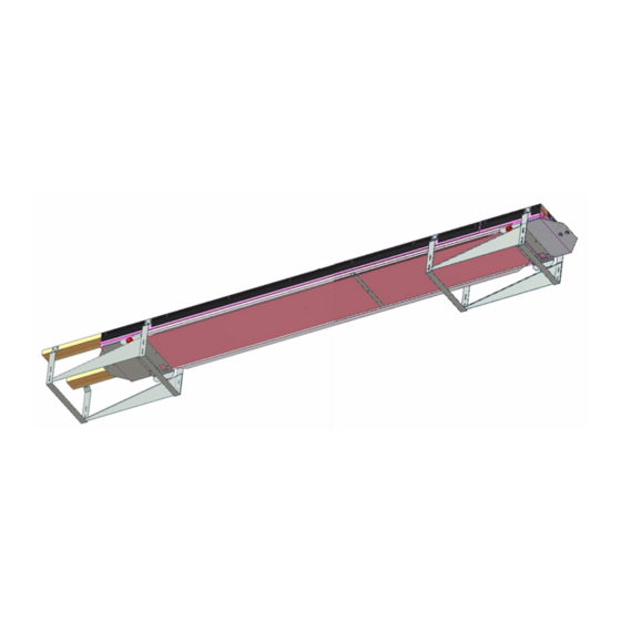
Page 5: Introduction
The Chore-Time TURBO-HOUSE Air Inlet is designed for use in confinement poultry buildings where the attic is used as an intake plenum. The TURBO-HOUSE Air Inlet system allows fresh air to enter through the ceiling for better air quality and temperature distribution. -
Page 6: Framing
Turbo-House Air Inlet Framing Chore-Time recommends insulation in BOTH the ceiling and the roof line of the attic for best year-round air system performance and temperature distribution control. Figure 1 below shows a cross-section of the TURBO-HOUSE Air Inlet ceiling construction options for blown insulation and rigid styrofoam board insulation. -
Page 7: Ceiling Slot And Mounting Board Length
Turbo-House Air Inlet Mounting and Installation of Inlet Components Ceiling Slot and Mounting Board Length For best results, the ceiling slot length should be an even increment of 8 feet [2.43 m]. The 2 x 4 [45 x 90 mm] mounting board should extend an additional 2 feet [610 mm] beyond the ends of the slot to accommodate the last Hanger and Ramp assembly and to avoid trimming 8 foot [2.43 m] parts (Inlet... -
Page 8: Ramp Hangers
Mounting and Installation of Inlet Components Turbo-House Air Inlet Ramp Hangers When installing Ramp Hangers start at the end towards the Inlet Power Unit. The Ramp Hangers are attached in pairs. Attach the 1st Ramp Hanger 6 inches [152mm] from the end of the Mounting Boards with #10 x 1"... -
Page 9: Ramps
Turbo-House Air Inlet Mounting and Installation of Inlet Components Ramps There are two different Ramps (left and right). Install the Ramps with the Hem on top and inside the Ramp Hangers with the Studs outward through the slots (See Figure). Secure with #10-24 Nuts. The Nuts should not be fully tightened at this time to allow for adjustment of the Ramps after the rest of the Inlet is assembled. -
Page 10: Carriages And Side Rails
Mounting and Installation of Inlet Components Turbo-House Air Inlet MV2308A... -
Page 11: Spring Return Kit (6" Part No. 39816) (9" Part No. 43134)
Turbo-House Air Inlet Mounting and Installation of Inlet Components MV2308A... -
Page 12: 1" Styrofoam Insulation Board (Deflector Board)
Mounting and Installation of Inlet Components Turbo-House Air Inlet 1" Styrofoam Insulation Board (Deflector Board) Step 1 . 1" Styrofoam Board must be purchased and cut to width shown in Step 2 to fit between the Side Rails. 6" System- Cut into 11.875 [403 mm] x 8’ pieces 9"... -
Page 13: Adding More Carriages, Rails, And Deflector Board
Turbo-House Air Inlet Mounting and Installation of Inlet Components Adding more Carriages, Rails, and Deflector Board Continue assembling Carriages, Side Rails, and Deflector Boards to the end of the system. Rest the remaining Carriages on the Ramps and attach Rails to them by bending over the Tabs exactly the same as you did in the previous steps. -
Page 14: End Connectors
Mounting and Installation of Inlet Components Turbo-House Air Inlet End Connectors An End Connector is required at each end of the Inlet row. Insert the End Connector Tabs into the slots of the end Carriage . Fasten with two #10-24 Flathead Machine Screws and two #10 Kepnuts. Bend the Tabs over as shown. -
Page 15: Top Seal
Turbo-House Air Inlet Mounting and Installation of Inlet Components Top Seal Cutting Insulation Board The styrofoam board used in the Inlet must be purchased and cut to fit into the Top Seal Channel Cut the styrofoam board into 2" x 2" x 8’ pieces. (See Figure below). -
Page 16: Attaching The Top Seal
Mounting and Installation of Inlet Components Turbo-House Air Inlet Attaching the Top Seal Starting at the Winch end of the Inlet, line up the cutouts in the 1st H-Channel with the 2nd Ramp Hanger and attach it to the 2 x 4 Mounting Boards at each obround hole with Wood Screws as shown. Continue fastening Top Seal pieces the entire length of the Inlet opening. - Page 17 Turbo-House Air Inlet Mounting and Installation of Inlet Components Top Seal Ends At the Winch end of the Inlet, line up the cutout in an H-Channel with the last Ramp Hanger and cut to fit the remaining Deflector Board as shown below. Cut 2" Foam to fit the H-Channel and slide it in place.
-
Page 18: Power Unit Hookup
Turbo-House Air Inlet Power Unit Hookup When properly installed, the TURBO-HOUSE Inlet requires approximately 7 lbs (3.17 kg) per 8 foot section of pull to close the inlet completely against the seal. The power unit must match the load requirements of the Inlet system. Two Chore-Time power units are available for use with the TURBO- HOUSE Inlet: the Light Duty Winch and the Heavy Duty Winch. -
Page 19: Attaching The Cable
Approximately 3.5" [8.9 cm] Controlling the Inlets The TURBO-HOUSE Inlets may be controlled by the Chore-Time Automatic Static Pressure Inlet Control. The pressure setting on the Inlet Control should be set to operate at 0.05" static pressure. The pressure sensor bottle(s) for the Inlet Control should be located so that the control senses the pressure drop across the inlet ONLY. -
Page 20: Spring Return
Spring Return Turbo-House Air Inlet MV2308A... -
Page 21: Part Numbers
Turbo-House Air Inlet Part Numbers MV2308A... - Page 22 Revisions to this Manual Page No. Description of Change New Manual Contact your nearby Chore-Time distributor or representative for additional parts and information. CTB Inc. P.O. Box 2000 • Milford, Indiana 46542-2000 • U.S.A. Phone (574) 658-4101 • Fax (877) 730-8826 E-Mail: ctb@ctbinc.com •...
Need help?
Do you have a question about the Turbo-House and is the answer not in the manual?
Questions and answers