Table of Contents
Advertisement
Advertisement
Table of Contents

Related Manuals for SKF CMPT CTU

Summary of Contents for SKF CMPT CTU
- Page 1 SKF Copperhead Transmitter Unit (CMPT CTU) for Machinery Fault Detection Part No. 32163100 Revision D Instruction Manual Copyright © 2011 by SKF Reliability Systems All rights reserved. Aurorum 30, 977 75 Luleå Sweden Telephone: +46 (0) 920 758 00, Fax: +46 (0) 920 134 40...
- Page 2 Telephone +46 (0) 920 758 00 FAX +46 (0) 920 134 40 For technical support, contact: TSG-EMEA@skf.com TSG-Americas@skf.com for customers in North and South America. Visit us at our web site www.skf.com/cm ® SKF is a registered trademark of the SKF Group...
-
Page 3: Table Of Contents
10 - 25 CTU CAN-bus CTU CAN-bus Connection ....................10 - 25 ....................10 - 27 CTU CAN Protocol ....................10 - 28 Services Unit Address ....................10 - 30 Overall Measurement Values ....................10 - 32 SKF Copperhead Transmitter Unit CMPT CTU TOC-3 Instruction Manual... -
Page 4: Description
Please read this instruction manual and the cautionary notes thoroughly. The SKF CTU is a digital vibration and temperature transmitter. It can be used as a part of a machinery fault detection system. The CTU performs three types of vibration signal process analysis –... -
Page 5: Features
(BNC switch) to measure either the accelerometer sensor buffered (not processed) vibration output or the sensor temperature output. The buffered vibration output can be monitored with an SKF Microlog or equivalent device. The CTU has a user configurable option to average the analog output signals so that rapid changes in vibration input do not cause annoying fluctuations in PLC/DCS or digital displays. - Page 6 The CTU can be located up to 100 m (330 feet) from the sensor with suitable shielded cabling. The CMPT DCL display/alarm module can be used along with the CMPT CTU module to have a stand-alone monitoring of processed vibration. A second DCL module can be used to optionally monitor temperature from a CTU connected to a CMPT 2310T or CMPT 2323T sensor.
-
Page 7: Specifications
500 Hz – 10 kHz Acceleration, g Accel RMS: 3 Hz – 10 kHz Accel Peak Hold: 3 Hz – 10 kHz Velocity, mm/s (inch/s) ISO: 10 Hz – 1 kHz 2 Hz – 1 kHz SKF Copperhead Transmitter Unit CMPT CTU Instruction Manual... - Page 8 Proportional to 0 °C to 120 °C Analog signal less than 4 mA or greater than 20 mA indicates a system fault. Auxiliary power: +24 V DC / 20 mA maximum Approvals: Emission 50081-2 Immunity 50082-2 SKF Copperhead Transmitter Unit CMPT CTU Instruction Manual...
-
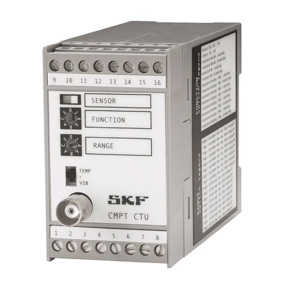
Page 9: Dimensions/Front Panel/Terminals
Range 0, Buffered signal input ON, Output averaging ON Range 1, Buffered signal input ON, Output averaging ON Range 2, Buffered signal input ON, Output averaging ON Range 3, Buffered signal input ON, Output averaging ON SKF Copperhead Transmitter Unit CMPT CTU Instruction Manual... - Page 10 Red (flashing) Vibration or temperature input signal exceeds full Scale Red/Green (flashing) Unit failure (return to SKF for repair) * The SENSOR OK lamp will be red if the temperature sensor is not connected. A 100 or a 120 resistor is required between CTU terminals 2 and 3 to avoid the red SENSOR OK lamp.
-
Page 11: Connector Assignment
Analog signal for temperature 4–20 mA VIB OUT Analog signal for processed vibration VIB COMMON OUT Analog signal common (ground) for vibration O–10 V VIB OUT Analog signal for processed vibration SKF Copperhead Transmitter Unit CMPT CTU 4-11 Instruction Manual... -
Page 12: Caution
The CMPT CTU should be installed by persons qualified to work with electrical instrumentation. Caution - Damage or injury can result • The CMPT CTU is powered by 24 V DE. Do not apply higher voltage. • Higher voltage (110 240 V AC) power may exist in the same proximity as the –... -
Page 13: Cmpt Ctu Output Signal Scales
CMPT CTU Output Signal Scales Vibration The accelerometer sensor and CMPT CTU unit provide processed vibration and temperature (optional) analog signals for use with a CTU module and for PLC/DCS systems for continuous monitoring. The scale of the CTU vibration analog output signal... - Page 14 0,84 IPS/V 2,8 IPS/V Ps. PK) Scale 0 to 0,84 IPS 0 to 2,8 IPS 0 to 8,4 IPS 0 to 28 IPS Velocity mode, ISO and Non-standard ISO Table 6-1: 6-14 SKF Copperhead Transmitter Unit CMPT CTU Instruction Manual...
- Page 15 L = vibration level in machine (gE, g, mm/s, IPS) V = measured voltage output from CTU (V) between 0 and 10 V DC S = full RANGE scale (gE, g, mm/s, IPS) of the CTU SKF Copperhead Transmitter Unit CMPT CTU 6-15 Instruction Manual...
-
Page 16: Temperature
V = measured voltage output from CTU (V) between 0 and 10 V DC T = (21.6 x V) + 32 Where as; T = temperature level in machine (°F) V = measured voltage output from CTU (V) between 0 and 10 V DC 6-16 SKF Copperhead Transmitter Unit CMPT CTU Instruction Manual... -
Page 17: Basic Instructions And Wiring Connections
Basic Instructions and Wiring Connections General Instructions The accelerometer sensor and CMPT CTU should be located within 100 m (300 feet) of each other. A suitable twisted and shielded pair of wires (22 AWG with 100 pF/m) should be used to connect the CMPT 2310 and CMPT 2323 accelerometer sensors to the CTU. -
Page 18: Normal Wiring As Vibration And Temperature (Optional) Transmitter
The sensor ground wire is connected to the inner shield of the sensor cable. This wire should be connected to ground (earth) inside the CMPT CTU enclosure. The sensors have a stainless steel over braid. The braid is for mechanical protection of the cable. The braid also acts as an outer shield. It is advised to isolate (shield) the sensor ground wire from the braid and local ground. - Page 19 Basic Instructions and Wiring Connections Normal Wiring as Vibration and Temperature (optional) Transmitter Basic connections (Basic CMPT CTU with wiring): Accelerometer CTU terminal ACC Signal / Power (White) ACC / TEMP signal Ground (Black) TEMP signal High (Red) Power +24 V DC...
-
Page 20: Normal Wiring As Vibration And Temperature (Optional) Transmitter With Cmpt Dcl Modules For Stand Alone Monitoring
The sensor ground wire is connected to the inner shield of the sensor cable. This wire should be connected to ground (earth) inside the CMPT CTU enclosure. The sensors have a stainless steel over braid. The braids for mechanical protection of the cable. The braid also acts as an outer shield. It is advised to isolate (shield) the sensor ground wire from the braid and local ground (earth). -
Page 21: Parallel Wiring With Secondary Ctu
To monitor a machine with two of the three possible analysis types – Acceleration Enveloping, Acceleration or Velocity – one accelerometer sensor and two CMPT CTU modules are wired parallel to one another. A secondary CTU module is wired parallel to a primary CTU. -
Page 22: Cmpt Ctu Output
CMPT CTU Output Each machine has its own normal vibration level depending on its function and design, supporting structure, and environment. The CMPT CTU is particularly useful for continuous detection of changes in machinery vibration and temperature. The CTU analog output signals can be monitored either by the PLC/DCS system or the CMPT DCL modules. - Page 23 1 800 or 3 600 r/min r/min r/min Good Good Good Satisfactory 0.75 Satisfactory Unsatisfactory Satisfactory (alert) Unsatisfactory Unsatisfactory (alert) Unacceptable (alert) (danger) Unacceptable Unacceptable (danger) (danger) Enveloped Acceleration Limits Table 8-7: SKF Copperhead Transmitter Unit CMPT CTU 8-23 Instruction Manual...
-
Page 24: Interface With Dataloggers And Vibration Systems
Interface with Dataloggers and Vibration Systems Interface with Dataloggers and Vibration Systems The CMPT CTU is equipped with a front panel BNC connector to enable connection to the buffered output signal of the connected accelerometer sensor. This enables use of the SKF MarlinVIBPAK and SKF Microlog dataloggers, or an equivalent vibration spectrum datalogger to safely and easily connect to the sensor without interference. -
Page 25: Ctu Can-Bus
CTU has an integrated 120 Ω resistor which can be disabled by removing the jumper shown in Figure 10-7, below. Figure 10-7: Location of jumper which can be removed to disable resistor SKF Copperhead Transmitter Unit CMPT CTU 10-25 Instruction Manual... - Page 26 Network problems are often caused by not using proper termination at both ends, wrong bit rates for cable lengths, incorrectly installed cables and/or poor signal quality. For more information, refer to: "Controller Area Network", by Konrad Etschberger, ISBN N 3-00-007376-0 http://en.wikipedia.org/wiki/Controller%E2%80%93area_network 10-26 SKF Copperhead Transmitter Unit CMPT CTU Instruction Manual...
-
Page 27: Ctu Can Protocol
As shown in Table 10-9 above, the network layer uses the ID bits [28-25] and [15-0] for protocol communication. The CTU service layers (higher layers) use bits [24-16] and the DLC and Data bytes from the CAN message. SKF Copperhead Transmitter Unit CMPT CTU 10-27 Instruction Manual... -
Page 28: Services
Source ID [0-5] Serial Serial number Table 10-11: Services boot-leader response Application response: Command Source Dest Data Remarks 0x80 Dest ID Source ID [0-5] Serial Serial number Table 10-12: Services application response 10-28 SKF Copperhead Transmitter Unit CMPT CTU Instruction Manual... - Page 29 6. Red: Destination (Broadcast to all CTUs 0xF1) The message in bitwise: 00010011110000000000000111110001 Response from CTU in application mode with serial number 0002-001746: 1301EF01 with 6 data bytes [0x00,0x02,0x00,0x00,0x06,0xD2] 00010011000000011110111100000001 0x09 0x80 0xEF 0x01 SKF Copperhead Transmitter Unit CMPT CTU 10-29 Instruction Manual...
-
Page 30: Unit Address
The bytes 1 to 6 (starting from left most) of the data represent the serial number and bytes 7 and 8 represent the new address for CTU (in this case 0x0010) Figure 10-10: Example of Edit transmit message 10-30 SKF Copperhead Transmitter Unit CMPT CTU Instruction Manual... - Page 31 6. Red: Destination (Broadcast to all CTU’s 0xF1) The message in bitwise (32 bit): 00010011110111100000000111110001 Response from CTU in application mode with serial number 0002-001746: 13DFEF01 with 6 data bytes [0x00,0x00] 00010011110111111110111100000001 0x09 0xEF 0xEF 0x01 SKF Copperhead Transmitter Unit CMPT CTU 10-31 Instruction Manual...
-
Page 32: Overall Measurement Values
Invalid parameter 0x0002 No write access 0x0003 Invalid condition 0x0004 Invalid state 0x0005 Zero sample rate 0x0006 No read access 0x0007 Invalid mode 0x0008 Invalid parameter value 0x0009 Algorithm not active 10-32 SKF Copperhead Transmitter Unit CMPT CTU Instruction Manual... - Page 33 The bit representation of data value (hex number 3D9AF3C0) is as the following: 00111101100110101111001111000000 S Exponent Fraction Sign (1 bit): bit position 31. Exponent (8 bit): bit position 23 to 30. Fraction (23 bit): bit position 22 to 0. SKF Copperhead Transmitter Unit CMPT CTU 10-33 Instruction Manual...
- Page 34 * 1/2 i=22 So in this case the equation could look like following: (-1)^0 * (1+1/8+1/16+1/64+1/256+1/512+1/1024+1/2048+1/8192+1/16384+1/3276 + 1/65536) * 2^(123-127) = 1 * 1,210678 * 2^-4 This represents value 0,075667375. 10-34 SKF Copperhead Transmitter Unit CMPT CTU Instruction Manual...
Need help?
Do you have a question about the CMPT CTU and is the answer not in the manual?
Questions and answers