
Subscribe to Our Youtube Channel
Summary of Contents for aFe Power Scorcher HD
- Page 1 Performance Chip Instruction Manual P/N: 77-43030 Make: Ford Model: F-250 Year: 1995-1997 Engine: V8-7.3L (td) Power Stroke Make: Ford Model: F-350 Year: 1995-1997 Engine: V8-7.3L (td) Power Stroke NOTE: Automatic Transmission Only! aFepower.com...
- Page 2 DISCLAIMER OF WARRANTY AND LIMITATION OF LIABILITY: Advanced FLOW Engineering, Inc. (also known as aFe or aFe POWER) and its successors, distributors, jobbers, and dealers (hereafter “SELLER”) shall in no way be responsible for the product’s improper use and service. It is the installer’s responsibility to check for proper installation and if in doubt, contact the manufacturer.
- Page 3 ECM Fitment Notes To make sure you have the correct aFe POWER part number, check your DPC-number and/or box code on ECM before installation. ECU: DPC-202 Supporting Box Codes: LKM, MIF, NAW, PRE, PRY, TDE, TEE, YBT and ZAA. Page 3...
-
Page 4: Parts List
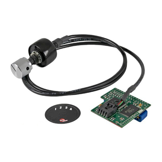
Parts List Performance Chip (2x) Nylon Cable Ties Scotch-Brite Knob Switch Position Switch Cable Sticker aFepower.com Page 4 Page 4 aFepower.com... - Page 5 Chip Installation BE AWARE All power to the vehicle must be DISCONNECTED prior to installation. Failure to do so could result in damage to your vehicles ECM. aFepower.com Page 5 Page 5 aFepower.com...
- Page 6 Removal of Stock Computer Disconnect both batteries and locate the ECM Connector under the hood on the driver’s side firewall. Loosen the bolt (10mm socket) located at the center of the ECM wiring harness plug. Inside the truck remove the 2 bolts (7mm socket) holding the ECM in place.
- Page 7 Stock ECM J3 Port Preparation Once you have the ECM removed, on the opposite end of the wiring harness plug is a small plastic or metal cover. Remove this cover gently. Inside this J3 port is a circuit board with double-sided contacts that must be cleaned of conformal coating. J3 Port contacts must be cleaned thoroughly, or the chip will not make proper contact with the ECM.
- Page 8 Installing the Switch/Chip Slide the connector cable into the chip. The proper orientation of the chip is with the circuit board of the chip and the switch cable on the larger side of the J3 port opening. aFepower.com Page 8 Page 8 aFepower.com...
- Page 9 Re-Installing the ECM Once you have properly mounted the chip, secure the chip to the ECM with a piece of package sealing or Duct tape. Be sure the box holding the computer in place does not bind the chip causing it to tilt and lose connection.
-
Page 10: Switch Settings
Switch Settings Install switch and sticker in a convenient location. Your installation is now complete. Thank you for choosing aFe POWER! 4 Position Settings 1) 50 HP with Built-in High Idle (when Cold) 2) 75 HP 3) 100 HP 4) HOT (Up to 140 HP) aFepower.com... - Page 11 Page left blank intentionally. aFepower.com Page 11 Page 11 aFepower.com...
-
Page 12: Warranty
Additionally, Incidental or consequential damages or cost, including installation and removal of part, incurred due to failure of aFe POWER product is not covered under this warranty. All warranty is limited to the repair and/or replacement of the aFe POWER product. - Page 13 advanced FLOW engineering, inc. 252 Granite Street, Corona, CA 92879 MAIN TEL: 951.493.7100 TECH: 812-518-1220 E-Mail: Tech@aFepower.com 06-81242 aFepower.com aFepower.com...
Need help?
Do you have a question about the Scorcher HD and is the answer not in the manual?
Questions and answers