Table of Contents
Advertisement
Available languages
Available languages
Advertisement
Table of Contents

Summary of Contents for wbox 0E-RCKMT700
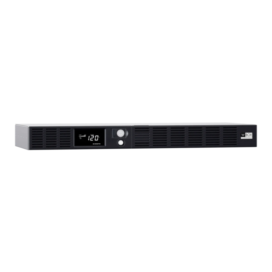
- Page 1 USER’S MANUAL Rackmount Series 0E-RCKMT700 K01-1101072-01 COPYRIGHT © 2020 ADI...
-
Page 2: Important Safety Instructions
IMPORTANT SAFETY INSTRUCTIONS (SAVE THESE INSTRUCTIONS) This manual contains important instructions that should be followed during installation and maintenance of the UPS and batteries. Please read and follow all instructions carefully during installation and operation of the unit. Read this manual thoroughly before attempting to unpack, install, or operate. CAUTION! To prevent the risk of fire or electric shock, install in a temperature and humidity controlled indoor area free of conductive contaminants. - Page 3 1. Ensure that the equipment plugged into the outlet does not exceed the UPS unit’s rated capacity (700VA/400W for 0E-RCKMT700). If the rated capacities of the unit are exceeded, an overload condition may occur and cause the UPS unit to shut down or the circuit breaker to trip.
-
Page 4: Basic Operation
BASIC OPERATION FRONT / REAR PANEL DESCRIPTION 1. LCD module display LCD shows all the UPS information with icons and messages. 2. Power On Indicator This LED is illuminated when the utility condition is normal and the UPS outlets are providing power, free of surges and spikes. -
Page 5: Replacing The Battery
BASIC OPERATION (CONTINUED) 9. Dry contact This port produces information for equipment that can read dry contact signals. 10. Circuit Breaker Located on the back of the UPS, the circuit breaker serves to provide overload and fault protection. Under normal operating conditions, the circuit breaker is depressed. 11. - Page 6 REPLACING THE BATTERY (CONTINUED) BATTERY REPLACEMENT PROCEDURE: Remove the right-side of the faceplate. Remove the three retaining screws on the cable protection cover then remove the cover. Disconnect the black and red cable. Remove the retaining screw of the cable connectors. Replace the new battery pack.
- Page 7 DEFINITIONS FOR ILLUMINATED LCD INDICATORS LINE MODE CAPACITY UPS STATUS DISPLAY DIGITAL VALUE DISPLAY DISPLAY SELECT SW PRESS Input Output % of % of Load Battery Cap. Voltage Voltage Load Batt Time Initial 5th(Return) (Overload) "V" : Illuminated, "X" : Not Illuminated, "--" : Either BATTERY MODE CAPACITY UPS STATUS DISPLAY...
-
Page 8: Troubleshooting
Shutdown your computer and turn the The unit is not providing battery power. UPS off. Wait 10 seconds and turn the UPS on. This should reset the unit. TECHNICAL SPECIFICATIONS MODEL 0E-RCKMT700 Capacity 700VA / 400W Nominal Input Voltage 90Vac to 140Vac Input Frequency... -
Page 9: Fcc Compliance Statement
TECHNICAL SPECIFICATIONS (CONTINUED) SYSTEM FUNCTION BLOCK DIAGRAM Surge EMI Filter Input Output Suppressor Charger Inverter AC/DC Battery Normal Mode Battery Mode FCC COMPLIANCE STATEMENT FCC Compliance Statement This device complies with part 15 of the FCC rules. Operation is subject to the following two conditions: (1) this device may not cause harmful interference, and (2) this device must accept any interference received, including interference that may cause undesired operation. -
Page 10: Limited Warranty And Connected Equipment Guarantee
LIMITED WARRANTY AND CONNECTED EQUIPMENT GUARANTEE Limited Warranty a. General Subject to the terms and conditions of this Limited Warranty, from the date of sale through the period of time for product categories specified in Section 1(b), ADI warrants its W Box Technologies products to be free from defects in materials and workmanship under normal use and service, normal wear and tear excepted. - Page 11 LIMITED WARRANTY AND CONNECTED EQUIPMENT GUARANTEE (CONTINUED) PRODUCT CATEGORIES WARRANTY PERIOD Video Surveillance Baluns 30 months Smoke Detectors 36 months 60 Months excluding HDD; 36 Months HDD DVR's, NVR's (included in recorder) HD Analog Cameras 60 Months IP Cameras 60 Months Racks 60 Months TV Mounts...
- Page 12 LIMITED WARRANTY AND CONNECTED EQUIPMENT GUARANTEE (CONTINUED) ANY PERSONAL INJURY, PROPERTY DAMAGE OR OTHER LOSS BASED ON ANY CLAIM AT ALL INCLUDING A CLAIM THAT THE PRODUCT FAILED TO GIVE WARNING. However, if ADI is held liable whether directly or indirectly for any loss or damage with respect to the products it sells, regardless of cause or origin, its maximum liability shall not in any case exceed the purchase price of the product, which shall be fixed as liquidated damages and not as a penalty and shall be the complete and exclusive remedy against ADI.
- Page 13 COST) of the equipment at of the time of the damage. CyberPower uses Orion Blue Book, or other a third- party valuation guides, or eBay, craigslist, or other source to establish that amount. The maximum liability is limited to $300,000 for the 0E-RCKMT700. All rights reserved. Reproduction without permission is prohibited.
- Page 15 Manuel de l’utilisateur Série Montage sur baie 0E-RCKMT700 COPYRIGHT © 2020 ADI...
- Page 16 CONSIGNES DE SÉ CURITÉ IMPORTANTES (VEUILLEZ CONSERVER CES INSTRUCTIONS) Ce manuel contient des instructions importantes qui devraient être appliquées lors de l’installation et de l’entretien du système d’ASI (Alimentation Sans Interruption ou Onduleur) et des batteries. Veuillez lire attentivement et respecter toutes ces instructions lors de l'installation et de l'utilisation de l'unité. Veuillez lire attentivement ce manuel avant de déballer, d'installer ou d'utiliser l’ASI.
- Page 17 1. Assurez-vous que l’équipement branché sur la prise ne dépasse pas la capacité nominale de l’ASI (700VA / 400W pour 0E-RCKMT700). Si les capacités nominales de l'unité sont dépassées, une surcharge peut se produire et entraî ner l'arrêt de l'ASI ou le déclenchement du disjoncteur.
- Page 18 FONCTIONNEMENT DE BASE DESCRIPTION DU PANNEAU AVANT/ARRIÈRE 1. Affichage du module DEL L'écran DEL affiche toutes les informations relatives à l'ASI au moyen d’icônes et de messages. 2. Voyant de mise sous tension Ce voyant DEL est illuminé quand l’alimentation secteur d’entrée est normale et que les prises de l'ASI fournissent une alimentation électrique sans surtension ni pointe de tension.
-
Page 19: Remplacement De La Batterie
FONCTIONNEMENT DE BASE (SUITE) 10. Disjoncteur Situé à l'arrière de l'onduleur, le disjoncteur fournit une protection contre les surcharges et les défauts. Dans des conditions normales de fonctionnement, le disjoncteur est enfoncé. 11. Entrée CA Branchez le cordon d’alimentation CA dans une prise correctement câblée et mise à la terre. 12. - Page 20 REMPLACEMENT DE LA BATTERIE (SUITE) PROCÉDURE DE REMPLACEMENT DE LA BATTERIE : Retirer le côté droit du panneau avant. Retirer les trois vis de fixation du couvercle de protection du câble, puis le retirer. Débrancher le câble noir et le câble rouge. Retirer la vis de fixation des connecteurs de câble.
- Page 21 DÉ FINITIONS DES VOYANTS LUMINEUX INDICATORS MODE EN LIGNE AFFICHAGE DE SÉLECTIONNE AFFICHAGE DU STATUT DE L’ASI AFFICHAGE DE LA VALEUR NUMÉRIQUE LA CAPACITÉ R SW % de % de la Cap. de Cap. de la Tension Tension Autono- APPUYER charge batterie d’entrée...
-
Page 22: Dépannage
L'unité ne fournit aucune Attendez 10 secondes, puis rallumez l'ASI. alimentation sur batterie. L'unité devrait alors être réinitialisée. SPÉ CIFICATIONS TECHNIQUES MODÈLE 0E-RCKMT700 Capacité 700VA / 400W Tension nominale d’entrée 90Vac à 140Vac Fréquence d’entrée 60 Hz +/- 3 Hz (auto-détection) - Page 23 SPÉ CIFICATIONS TECHNIQUES (SUITE) SCHÉMA DE PRINCIPE DU FONCTIONNEMENT DU SYSTÈME Surge EMI Filter Input Output Suppressor Charger Inverter AC/DC Battery Normal Mode Battery Mode DÉ CLARATION DE CONFORMITÉ AUX NORMES DE LA FCC DE SÉ CURITÉ Déclaration de conformité aux normes de la FCC Cet appareil est conforme à...
- Page 24 GARANTIE LIMITÉ E ET GARANTIE DE L'É QUIPEMENT CONNECTÉ Limited Warranty a. Généralités Sous réserve des modalités de la présente garantie limitée, à compter de la date de vente et pendant la période de garantie applicable aux catégories de produits précisées au paragraphe 1(b), ADI garantit que ses produits W Box Technologies sont libres de tout vice de matériaux et de fabrication dans des conditions d’utilisation et d’entretien normales, sauf l’usure normale.
- Page 25 GARANTIE LIMITÉ E ET GARANTIE DE L'É QUIPEMENT CONNECTÉ (SUITE) PRODUCT CATEGORIES WARRANTY PERIOD Boutons de maintien 30 mois Baluns de vidéosurveillance 30 mois Détecteurs de fumée 36 mois 60 mois sauf HDD; 36 mois HDD DVR, NVR (inclus dans l’enregistreur) Caméras analogiques HD 60 mois Caméras IP...
- Page 26 établie pour le produit de remplacement. ADI se réserve le droit de donner une note de crédit plutôt que de remplacer le produit. Si l’on établit que le produit WBox Technologies n’est pas défectueux ou que son mauvais fonctionnement résulte d’une utilisation abusive ou de dommages causés par l’utilisateur, le produit sera retourné à...
- Page 27 Nous utiliserons le Livre Bleu Orion, OU un autre guide d’estimation d’une tierce partie, ou eBay, Craigslist ou une autre source pour établir ce montant. Notre responsabilité maximale est limitée à 300 000 $ pour le 0E-RCKMT700. Tous droits réservés. Reproduction sans autorisation interdite.
Need help?
Do you have a question about the 0E-RCKMT700 and is the answer not in the manual?
Questions and answers