Table of Contents
Advertisement
Quick Links
Advertisement
Table of Contents

Related Manuals for Pulsar Flow Monitor

Summary of Contents for Pulsar Flow Monitor
- Page 1 Flow Monitor INSTRUCTION MANUAL...
- Page 3 ARRANTY AND IABILITY Pulsar Process Measurement Limited guarantee for a period of 2 years from the date of delivery that it will either exchange or repair any part of this product returned to Pulsar Process Measurement Limited if it is found to be defective in material or workmanship, subject to the defect not being due to unfair wear and tear, misuse, modification or alteration, accident, misapplication or negligence.
-
Page 5: Table Of Contents
........................1 About this Manual ............................1 About the Flow Monitor ..........................2 Product Specification............................3 EU Declaration of Conformity ........................4 ........................5 Unpacking ................................ 5 Power Supply Requirements ........................... 5 Location ................................5 Dimensions ..............................6 Cable Entry .............................. 7 Terminal Connection Detail ........................ - Page 6 Setpoint ..............................42 Limits ..............................42 Trim ............................... 43 Failsafe ..............................43 Totaliser Parameters ............................44 Setup ............................... 44 Totalisers ..............................45 Tot. Audit ............................... 45 System Parameters ............................46 Passcode ..............................46 System Information ..........................46 Date & Time ............................47 Daylight Saving Time ...........................
-
Page 7: About This Manual
Congratulations on your purchase of a Pulsar Flow Monitor System. This quality system has been developed over many years and represents the latest in high technology ultrasonic flow and velocity measurement and control. It has been designed to give you years of trouble free performance, and a few minutes spent reading this operating manual will ensure that your installation is as simple as possible. -
Page 8: About The Flow Monitor
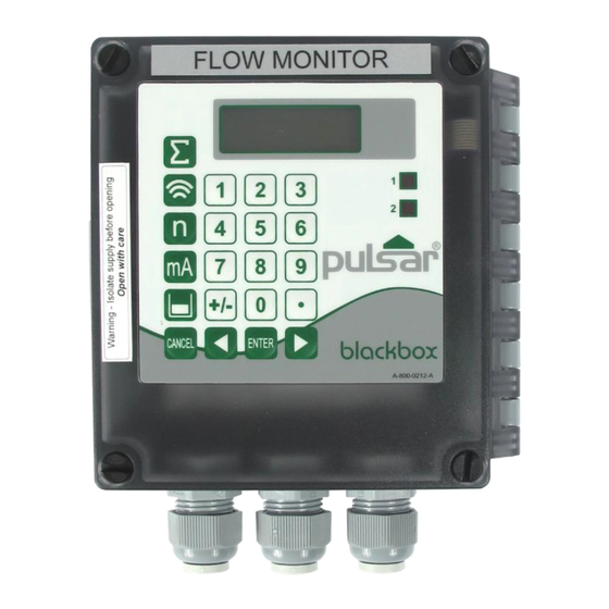
About the Flow Monitor The Pulsar Flow Monitor has been designed to provide a simple interface to the Pulsar Flow Pulse Sensor. Housed in an IP67 enclosure the product is ideally suited to applications where velocity monitoring, reporting or control is required. -
Page 9: Product Specification
DC 22 - 28V 10W maximum power (typically 8W) 2A ‘T’ 20mm Mains Fuse DC Fuse Self Resetting Type Pulsar Process Measurement Limited operates a policy of constant development and improvement and reserve the right to amend technical details as necessary. Page 3... -
Page 10: Eu Declaration Of Conformity
EU Declaration of Conformity Page... -
Page 11: Unpacking
Pulsar Process Measurement Limited. Power Supply Requirements The Flow Monitor can operate from AC supply or from a DC battery. The AC is 85 – 264V, 50/60Hz. The DC is 22 - 28V. In all cases the Flow Monitor will typically consume 8W of power, with a maximum of 10W. -
Page 12: Dimensions
Dimensions The dimensions of the mounting holes are as shown below. The Flow Monitor should be mounted by drilling four holes suitable for size 8 screws (length and type to suit your application) And fix all four screws by removing the top cover to access the pre-moulded mounting holes which are located in the base of the enclosure under the lid retaining screws. -
Page 13: Cable Entry
The full dimensions of the enclosure are as shown below. Cable Entry There are 3 x M20 cable glands, suitable for 6 – 12mm cables, fitted to the base of the Flow Monitor enclosure. Important Information All cable glands should be tightened to the manufacturer’s specifications. -
Page 14: Terminal Connection Detail
Terminal Terminal 0V (GND) 24V DC *RS485 SCR RS485 + RS485 - Cable Screen 3 or 6 Not connected *On older versions of Flow Monitor the RS485 Screen is connected to terminal 21 (not shown on the above diagram). Page... -
Page 15: Terminal Connections
Terminal Connections Power The Flow Monitor can be powered from mains AC or from a DC source/battery and where a backup DC power source is connected it will automatically take over in the event of AC power failure; DC will automatically power the unit. -
Page 16: Ac And Fuse Location
Preparation for Operation Before switching on, check the following: ✓ The Flow Monitor is mounted correctly and is in a ‘safe’ area. ✓ The power supply is correctly installed. ✓ The relays are connected correctly. - Page 17 Your Flow Monitor can be programmed directly via the integral keypad. Page 11...
-
Page 18: Operating The Controls
Operating the Controls Display Whilst in the Run Mode it will display the current flow or velocity reading and its units of measurement, along with the mA output and status messages with regards to the communication status and Fail Safe Mode. When in Program mode, the display is used to read information on the menu system, the parameter number and parameter details and values, which can be entered. -
Page 19: Keypad
Run Mode. Pressing the hot key once will display the first parameter, then repeated pressing will display the others, then the Flow Monitor reverts to Run Mode. In program mode, they have different functions, the functions are shown below. - Page 20 Menu Keys The menu keys are used to navigate around the built in menu system and have the following functions: Menu Key Function 1) Arrow keys for moving left and right around the menu system. 2) Used in test mode to simulate the flow or velocity moving up and down.
-
Page 21: Run Mode
All modes are now described. Run Mode This mode is used once the Flow Monitor has been set up in program mode. It is also the default mode that the unit reverts to when it resumes operation after a power failure. -
Page 22: Program Mode
Program Mode This mode is used to set up the Flow Monitor or change information already set. You must use either the on-board keypad (standard) or alternatively the unit can be set up with a Hand Held Calibrator (optional), which must be connected to the Flow Monitor via the RS 232 Serial Interface. - Page 23 When you have finished, press CANCEL to go back to the previous level. When you have reached the top level, then the Flow Monitor will ask for confirmation before allowing you to go back into run mode. This is done by pressing ENTER at the display prompt.
-
Page 24: Test Mode
Test Mode Test mode is used to simulate the application and confirm that all parameters and relay setpoints have been entered as expected. During simulation, there is a choice of whether the relays will change state (hard simulation) or not (soft simulation), but the LED’s will always change state to indicate that the relay setpoints have been activated, and the mA output will change. -
Page 25: Using The Rs232 Serial Interface
Factory Defaults P930, as described in Chapter 5 Parameter Guide. The date (P931) and time (P932) in the Flow Monitor were set at the factory, but may need checking or amending if, for example the application is in a time zone other than GMT, see Chapter 5 Parameter Guide for full details. - Page 26 This page left blank intentionally Page...
-
Page 27: Menu System Diagrams
This chapter describes all of the parameters in your Flow Monitor, in the order they appear in the menu system. Menu System Diagrams Shown below is a set of charts to show you how all the various parts can be found using the menu system. -
Page 28: Application Menu
Application Menu Device Operation Comms P102 P141 Mag Thresh Protocol P104 P142 Damping Device Addr P105 P143 Averaging Device Baud P108 P144 Cal factor Parity P110 P145 Pipe ID Stop Bits P111 P146 Noise Adapt Format P113 P147 Step Resp Tx Delay P148 P115... -
Page 29: Relays Menu
Relays Menu Relay 1 Relay 2 P210 P220 R1 Type R2 Type P211 P221 R1 Function R2 Function P212 P222 R1 I/D R2 I/D P213 P223 R1 Setpoint 1 R2 Setpoint 1 P214 P224 R1 Setpoint 2 R2 Setpoint 2 P217 P227 R1 Closures... -
Page 30: Display Menu
Display Menu Options Failsafe Auxiliary P800 P808 P815 Display Source Fail Mode Aux Source P809 P801 Fail Time Dec.Places P802 Meas.Unit P803 Volume Unit P804 Time Unit P805 Display Offset P806 Displ Converter Page... -
Page 31: Ma Output Menu
mA Output Menu Range Operation Setpoints Limits Trim Fail Safe P830 P831 P834 P836 P838 P840 mA Range mA Mode Low Value Low Limit Low Trim Fail Mode P835 P837 P839 High Value High Limit High Trim Totaliser Menu Setup Totaliser Tot.Audit P822... -
Page 32: System Menu
System Menu Pass Code Sys. Info Date & Time Daylight Save P921 P926 P931 P970 Software Rev Enable Code Date DST Enable P922 P927 P932 P971 Passcode Hardware Rev Time DST Difference P928 P933 P972 Serial No. Date Format DST Start Time P929 P973 Site Ident... -
Page 33: Test Menu
Test Menu Simulation Hardware P980 P991 Simulate Hard Test P981 P992 Increment mA Out Test P982 P993 Rate Relay Test P983 Test Max P984 Test Min Page 27... -
Page 34: Application Parameters
Parameter Listing This section describes all of the parameters. Any parameter can be reset to its default, by pressing the hot key, whilst in program mode. Application Parameters Operation P102 Mag Threshold This parameter sets the sensitivity of FlowPulse sensor. The Mag Threshold value sets the required level of signal above the minimum signal before the FlowPulse decides it is seeing flow. - Page 35 E.g. if the parameter is set to 2300, then the corresponding flow index would be 100. The Flow Pulse via the Flow Monitor will not report any flow unless the flow indicator exceeds 100 on the flow index.
- Page 36 P128 TrackThrAdd This is only activated when noise floor is raised, such that the noise floor is more than P111 away from the normal floor without flow. This causes the flow to be tracked at a lower flow index so that compensation can be applied.
-
Page 37: Device Comms
Device Comms P141 Protocol This parameter determines the communication protocol that the processor uses to initialise the FlowPulse sensor. Option Description 0 = Modbus RTU (Default) Modbus RTU with hexadecimal data 1 = Modbus ASCII Modbus ASCII with ASCII data P142 Device Address This parameter determines the address of the FlowPulse sensor that the processor is connected to. - Page 38 P146 Extended Format This parameter determines the data format that the processor uses to communicate with the FlowPulse sensor. Option Description 0 = Unsigned Integer (Default) Unsigned integer data 1 = Signed Integer Signed integer data 2 = Float Motorola Format Motorola floating point format 3 = Float IEEE Format IEEE 754 floating point format...
-
Page 39: Relay Parameters
Relay Parameters All relay related parameters are prefixed with a 2**. The second digit of the three figure parameter number denotes the relay number as follows: 21* parameters for Relay 1 22* parameters for Relay 2 The third digit selects specific parameters for the setting up of the relays, which can be selected individually and results in the following parameter numbers for each relay. -
Page 40: Alarms
Alarms P210, P220 =1 (Alarm) The second parameter for each relay determines the function of the alarm. P211, P221 - Relay Function This parameter defines what function the alarm will respond to as follows. Option Description 0= Off (Default) Relay will not operate. Alarm is based on the flow rate and the type of flow alarm (P212, 222) and two setpoints must be 1= Flow... - Page 41 Alarm ID Description Setpoints Relay goes “ON” when 1=General (Default) P213, 223 is ON the value reaches the ON Setpoint; setpoint and goes “OFF” P214, 224 is OFF when the value reaches Setpoint the OFF setpoint. Relay goes “ON” when 2= High ON>...
- Page 42 The fourth parameter and the fifth parameter for each relay set the Alarm “ON” and “OFF” points. For a high alarm the “ON” is set higher than “OFF”. For low alarm then “ON” is set lower than “OFF”. See the appropriate alarm ID, table (P212, 222) for further information.
-
Page 43: Control
Control P210, P220 = 2 (Control) When a relay is being set up as a control relay, the second parameter that will be displayed in the menu determines its function. P211, P221 - Relay Function, This function is used, where it is required to energise the relay to switch a device, such as a pump, ON and de-energise the relay to switch the device OFF. -
Page 44: Totaliser
Totaliser P210, P220 = 3 (Totaliser) When a relay is set up as a totaliser relay, the second and third parameters that will be displayed in the menu determine the frequency and duration of the relay pulse. P213, P223 - Relay Setpoint 1 The factor by which the on board totaliser (P820) should be multiplied by to provide a relay closure, giving the frequency of the pulse. -
Page 45: Display Parameters
Display Parameters Options P800 Display Source This parameter determines whether the Flow Monitor uses the Flow or the Velocity. Option Description 1 = Flow (Default) Display shows flow readings 2 = Velocity Display shows velocity readings P801 Decimal Places This parameter determines the number of decimal places on the reading during run mode. -
Page 46: Failsafe
P804 Time Unit The value of this parameter determines the time unit of flow and velocity readings. Option Description 1 = per second (Default) Display flow per second 2 = per minute Display flow per minute 3 = per hour Display flow per hour 4 = per day Display flow per day... -
Page 47: Auxiliary
P809 Fail-safe Time In the event of a fail-safe condition the failsafe timer determines the time before fail-safe mode is activated. Default = 2min If the timer activates, the unit goes into fail-safe as determined by P808 (Display) and P840 (Output). When this happens, you will see the message “Failed Safe!”... -
Page 48: Operation
Operation P831 Output Mode This parameter determines the output mode of the mA output, from the following. Option Description 0= Default (Default) mA output follows P800 (Display Source) 1 = Flow mA output according to flow reading 2 = Velocity mA output according to velocity reading Setpoint By default, the mA Output will represent the 0% (0 or 4mA dependant on... -
Page 49: Trim
Trim P838 Output Low Trim If the device you are connected to is not calibrated, and not showing the low value, then you can trim it using this parameter. You can either type in the offset directly or use the arrow keys to move the output up and down until you get the expected result on the device that is connected. -
Page 50: Totaliser Parameters
Totaliser Parameters Setup P822 Totaliser Enable This parameter determines if the totaliser is enabled or not, the options are as follows: Option Description 0 = No (Default) Totaliser is disabled 1 = Yes Totaliser enabled P823 Totaliser Decimal This parameter determines the number of decimal places in the totaliser during run mode. -
Page 51: Totalisers
P825 Totaliser Log Time This parameter sets the time at which the totalisers are stored in non-volatile memories Default = 00:00 Totalisers P820 System Totaliser Displays the current value of the, non-resettable totaliser. During run mode this totaliser can be viewed via the “Totaliser” hot key. Unlike the resettable totaliser this totaliser cannot be reset whilst in run mode, it can however be reset whilst in program mode by accessing P820 Totaliser and entering zero. -
Page 52: System Parameters
1997, but this can be changed to another value from 0 to 9999. System Information The following three parameters do not affect how the unit performs, but details contained within them may be required, by Pulsar, when making technical enquiries. P926 Software Revision... -
Page 53: Date & Time
Date & Time P931 Date This parameter shows the current date, in the format as set by P933 (Date Format) and can be reset if required. P932 Time This parameter shows the current time and can be reset if required, in the format HH: MM (24-hour format). - Page 54 P973 Start Day Use this parameter to enter the day of the week (P974) that Daylight Saving Time is to start. Option Description 2 = Monday DST will start on a Monday 3 = Tuesday DST will start on a Tuesday 4 = Wednesday DST will start on a Wednesday 5 = Thursday...
- Page 55 P975 Start Month This parameter is used to select the month in which Daylight Saving Time is to start. Option Description DST will start during the month of January 1 = January DST will start during the month of February 2 = February DST will start during the month of March 3 = March (Default)
- Page 56 P978 End Week This parameter will determine the week of the month (P975) in which Daylight Saving Time is to end. Option Description DST will end on day (P977) in the first week 1 = Week 1 (P978) of the month (P979). DST will start on day (P977) in the second 2 = Week 2 week (P978) of the month (P979).
-
Page 57: Test Parameters
Test Parameters Simulation P980 Simulate Test mode is used to simulate the application and confirm that all parameters and relay setpoints have been entered as expected. During simulation, there is a choice of whether the relays will change state (hard simulation) or not (soft simulation), but the LED’s will always switch according to how the relays have been programmed, and the output will change accordingly. -
Page 58: Hardware
P983 Test Max This parameter determines the maximum of the simulated measurement values. Default = 1000 P984 Test Min This parameter determines the minimum of the simulated measurement values Default = 0 Hardware P991 Hard Test When this parameter is selected, the unit will test the following in turn: •... - Page 59 Check that the correct Device Address (Modbus ID) for the “P102 Fail” message is displayed FlowPulse has been entered into P142 of the Flow Monitor. Ensure FlowPulse sensor is Current velocity reads zero but you mounted correctly and in know there is flow movement.
- Page 60 Incorrect disposal can cause adverse effects to the environment. Dispose of the device components and packaging material in accordance with regional environmental regulations including regulations for electrical \ electronic products. Transducers Remove power, disconnect the Transducer, cut off the electrical cable and dispose of cable and Transducer in accordance with regional environmental regulations for electrical \ electronic products.
- Page 61 Page 55...
Need help?
Do you have a question about the Flow Monitor and is the answer not in the manual?
Questions and answers