Table of Contents
Advertisement
Quick Links
DESCRIPTION
8310-881
Hard-wired transmitter with flag
75.0023.01 ALLEGION 8310-880 900 MHZ TRANSMITTERS_RECEIVERS 20200612
75.0023.01 ALLEGION 8310-880 900 MHZ TRANSMITTERS_RECEIVERS 20200612
8310-880 900 MHZ TRANSMITTERS & RECEIVERS
3
2
5
6
7
8310-882
8310-885
connectors
4
1
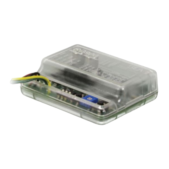
1. Antenna
2. Blue LED (Activation)
3. Red LED (Learn)
4. Tri-color LED (signal strength)
5. DIP switches
6. Delay Learn button
7. Delay Learn potentiometer
8. No-Delay Learn button
8
8310-883
Touchless retrofit transmitter for touch-to-touchless
plate retrofit applications
8310-884
8310-886
Page 1 of 8
Page 1 of 8
Advertisement
Table of Contents

Summary of Contents for Allegion 8310-880
- Page 1 8310-882 8310-883 8310-884 8310-885 8310-886 Hard-wired transmitter with flag Touchless retrofit transmitter for touch-to-touchless connectors plate retrofit applications 75.0023.01 ALLEGION 8310-880 900 MHZ TRANSMITTERS_RECEIVERS 20200612 75.0023.01 ALLEGION 8310-880 900 MHZ TRANSMITTERS_RECEIVERS 20200612 Page 1 of 8 Page 1 of 8...
- Page 2 DO NOT attempt any internal repair of the components. All repairs and/or component replacements must be performed by Allegion. Unauthorized disassembly or repair: 1. May jeopardize personal safety and may expose one to the risk of electrical shock. 2. May adversely affect the safe and reliable performance of the product resulting in a voided warranty.
- Page 3 6. Install the 900 MHz wireless receiver in the header (sold separately). Touchless Retrofit Transmitter COM NO TOUCHLESS PLATE 75.0023.01 ALLEGION 8310-880 900 MHZ TRANSMITTERS_RECEIVERS 20200612 75.0023.01 ALLEGION 8310-880 900 MHZ TRANSMITTERS_RECEIVERS 20200612 Page 3 of 8 Page 3 of 8...
- Page 4 NOTES: 1. If “Delay Learn” button is used, adjust potentiometer (1 – 30 seconds). Page 4 of 8 Page 4 of 8 75.0023.01 ALLEGION 8310-880 900 MHZ TRANSMITTERS_RECEIVERS 20200612 75.0023.01 ALLEGION 8310-880 900 MHZ TRANSMITTERS_RECEIVERS 20200612...
-
Page 5: Signal Strength Indicator
LED on receiver. Green = strong signal Red = weak signal Yellow = medium signal 75.0023.01 ALLEGION 8310-880 900 MHZ TRANSMITTERS_RECEIVERS 20200612 75.0023.01 ALLEGION 8310-880 900 MHZ TRANSMITTERS_RECEIVERS 20200612 Page 5 of 8 Page 5 of 8... -
Page 6: Battery Replacement
(2) and disassemble. (CR2032) battery, observing polarity, and reassemble. PUSH PLATE (8310-886) Replace 2 AAA batteries observing polarity. Page 6 of 8 Page 6 of 8 75.0023.01 ALLEGION 8310-880 900 MHZ TRANSMITTERS_RECEIVERS 20200612 75.0023.01 ALLEGION 8310-880 900 MHZ TRANSMITTERS_RECEIVERS 20200612... -
Page 7: Troubleshooting
Norm Conformance: All: FCC, IC Specifications are subject to change without prior notice. All values measured in specific conditions. 75.0023.01 ALLEGION 8310-880 900 MHZ TRANSMITTERS_RECEIVERS 20200612 75.0023.01 ALLEGION 8310-880 900 MHZ TRANSMITTERS_RECEIVERS 20200612 Page 7 of 8 Page 7 of 8... -
Page 8: Fcc/Ic Compliance
Allegion at 1-877-671-7011. If you must wait for the following workday to call Allegion, leave the door inoperable until satisfactory repairs can be made. Never sacrifice the safe operation of the automatic door or gate for an incomplete solution.
Need help?
Do you have a question about the 8310-880 and is the answer not in the manual?
Questions and answers