Advertisement
Quick Links
Advertisement

Subscribe to Our Youtube Channel
Related Manuals for Itel RDS

Summary of Contents for Itel RDS
- Page 1 RDS ENCODER User manual Rev 2.3 1‐2014 Firmware 2.1.0.0...
- Page 2 RDS Encoder User Manual Rev 2.2 Declaration of conformity according to directive 99/5 Itel Elettronica e Telecomunicazioni SNC – Via S.Penna, 82 06132 S.Andrea delle Fratte Perugia (PG) hereby declares that the product: RDS CODER and its optional accessories : OPT1: MPX CODER OPT2: LAN INTERFACE OPT3: AUDIO CHANGEOVER intended for RDS and MPX signal generation, manufactured by Itel Elettronica e Telecomunicazioni SNC, complies with essential requirements of article 3 and other relevant provisions of Directive 1999/5/EC, when used for its intended purpose. Health and safety requirements pursuant to Article 3.1.a Standards applied: EN60125: 1989/A1:1992/A2:1994 Protection requirements concerning electromagnetic compatibility pursuant to article 3.1.b Standards applied: EN301489‐1 V 1.8.1 ; EN301489‐11 V 1.3.1. Perugia 10/02/2012 Itel Elettronica e Telecomunicazioni SNC mail: info@itel.it A.Tomassini ...
- Page 3 RDS Encoder User Manual Rev 2.2 WARNING Before attempting any operation, please follow the safety instructions contained in the following paragraph. ITEL SNC declines any liability for damage to people or things due to non‐compliance, even if partial, of the following indications • Ensure that the supply voltage corresponds to what is indicated on the apparatus. • Ensure that the electrical system is equipped with a ground connection. • Use only power sockets and cables with ground connection • Disconnect power before attempting any operation inside the device. • The power cutting device is the power cord, so this should be easily accessible and the socket must be positioned close to the apparatus. • Any operation involving the access to internal parts must be performed only by trained service personnel. 3 ...
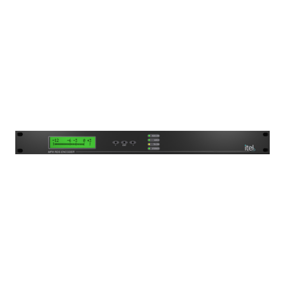
- Page 4 RDS Encoder User Manual Rev 2.2 Front panel: Leds on front panel: • RDS ON: is on when the RDS encoder is active • LOCK: is on when the encoder is synchronized to an external 19KHz signal • TA ON: is on when the Traffic Announce flag is being transmitted • STEREO: is on when the internal stereo coder is active Rear panel: Connector and settings on the rear panel • RIGHT IN (XLR‐F) right channel input for the stereo coder [1] • LEFT IN (XLR‐F) left channel input for the stereo coder [1] • MPX OUT ...
- Page 5 RDS Encoder User Manual Rev 2.2 External control port and input equivalent circuit: PIN Description Notes 1 M/S + 2 TA + 3 SPARE + 4 +12V Max 50 mA 5 +12V Max 50mA 6 M/S ‐ 7 TA ‐ 8 SPARE ‐ 9 Frame ground Connection example for remote switching of TA flag 470 Ω 1/4W i Note: The external connector must be enabled via the specific menu on the display or using the configuration program (RdsProg). 5 ...
- Page 6 Stereophonic modulation, using external audio processor / stereo encoder and FM modulator, or STL transmitter, as a RDS signal mixer. Pilot reference for the RDS encoder has to be set to external. FM Modulator / STL Transmitter RF OUT MPX INPUT SCA INPUT RDS Encoder LEFT INPUT RIGHT INPUT MPX OUT MPX IN RDS OUT PILOT SYNC input On HW>3.0 the pilot tone is extracted directly from MPX Audio Processor / Stereo encoder...
- Page 7 RDS Encoder User Manual Rev 2.2 Stereophonic / Monophonic modulation, using internal audio stereo encoder. Pilot reference for the RDS encoder has to be set to internal. FM Modulator / STL Transmitter RF OUT MPX INPUT SCA INPUT RDS Encoder LEFT INPUT RIGHT INPUT MPX OUT MPX IN RDS OUT PILOT SYNC From audio source ...
- Page 8 RDS Encoder User Manual Rev 2.2 Navigation / Editing: The windows can be scrolled through using the “left/increment” and “right/decrement” keys on the front panel. To modify editable parameters, once entered into the desired window, press the button “Edit/Enter”. RDS Enabled: ON TA:OFF MS:MUS Pressing the “edit/enter” key, an asterisk “*” will appear near the first editable item RDS Enabled: ON* TA:OFF MS:MUS Pressing the “left/increment” or “right/decrement” keys the “*” cursor can be positioned on the other editable items on the selected window. RDS Enabled: ON TA:OFF* MS:MUS Wishing now to modify the value of TA flag, press again the “Edit/Enter” key: a “<” symbol will appear near then parameter indicating that it is in editing state. RDS Enabled: ON TA:OFF< MS:MUS Pressing now “Right/Increment” and “Left/Decrement” keys, the value of selected parameter can be changed. RDS Enabled: ON TA:ON < MS:MUS Once the desired value is set, press again the “Edit/Enter” key. The symbol will return to “*”, to indicate that you are back in navigation state. If needed, you can then go and change other parameters into the same window. ...
-
Page 9: Station Name
RDS Encoder User Manual Rev 2.2 Menus on firmware rev. 2.0.0.0 Firmware version window: Itel RDS Encoder Hw 2.0.0.0 Sw: 2.0.0.0 The product name is shown and its firmware version. No parameter can be modified here. Station ID window: Station ID: STATION NAME In this window, a user definable label is shown to identify the coder and the site to which the coder is assigned. The text shown is a label only and will not be transmitted in any RDS block. Audio levels window : ‐12 ‐6 ‐3 0 +3 L | | |||||||||||| |||| | | | L | | |||||||||||| |||| | | | | | |||||||||||| |||| ... - Page 10 RDS Encoder User Manual Rev 2.2 RDS flags window: RDS Enabled: ON TA:ON MS:MUS The encoder, TA (Traffic Announce) and M/S (Music/Speech) flags status are shown. All parameter are editable and, furthermore, the ON/OFF status of the encoder and the TA status are also indicated by the front panel leds. PS, PI and PTY window: PS:MY RADIO PI:55FF PTY:09:Varied The program station name (PS), its PI code and PTY are shown on this window. No parameter can be modified. Radiotext window: Radiotext : Itel RDS Encoder It is shown if the encoder is enabled and allowed to send the Radiotext block and, if enabled and active, the current radiotext being transmitted. If the current radiotext is transmitted as a radiotext‐plus string, the first row label will turn into “Radiotext+:”. Note: as the radiotext string is longer than the display size, it will be visualized 20 chars at a time. The resulting scrolling animation will not be present on the radiotext string being transmitted. 10 ...
- Page 11 RDS Encoder User Manual Rev 2.2 External control port status and enabling: Ext port enab.: OFF TA: OFF MS:OFF SP:MUS In the upper row, the external control port status is shown. To remotely control the TA and M/S flags with external devices (eg. your radio automation system), it is necessary to enable the external port. Note: when the external control port is enabled, it will not be possible to control these flags through the Rd‐Link software. The lower row shows the input status in real time and it is useful, during the installation process, to verify the correct connection of the external devices. Encoder synchronization window: VCXO [ ] |||||||||||| 19K Ref: INT On the encoders provided with external synchronization input, the synchronization window is available and it allows the selection of internal or external reference and the operating status. During normal operation, both with internal or external reference, the bar should be about half scale. If the bar reach extreme values, it means that the synchronization signal has a tolerance greater than +/‐ 2Hz. Note: If the encoder is used with monophonic signals, the reference must be set on INTERNAL. With a stereo signal, you must enable the external reference. On Hw>3.0 the pilot reference, as a default setting, is extracted from the incoming MPX signal. If a separated clock sync is needed, the internal jumper J1 has to be set to "BNC" position and a 19KHz clock signal has to be injected into "PILOT SYNC" connector. ...
- Page 12 RDS Encoder User Manual Rev 2.2 Configuration software: The configuration software is supplied for setting up all coder features. The connection is through a serial port 9600 baud 8 databits, no parity, 1 stop bit. Main window: In the main window you can select the COM port used for communication with the RDS encoder To verify communication, once you the serial port is selected, connect the encoder to the PC and press the button "Get Info". If the communication is correct, the product type and its firmware version will be shown. You can then, by pressing the "Read Coder" button, read all the informations stored into the coder. Anyway, any block (flags, Radiotext, PS or Af List) can be read individually, using the “Read” button into the related tab. To speed up programming is in fact possible to edit and transfer all blocks or read and write only what you need to change, eg. the alternate frequencies or PSNs, leaving all others unchanged. The programmed setup can be saved and reloaded from disk using the pull down menu "File". 12 ...
- Page 13 RDS Encoder User Manual Rev 2.2 Encoder Flags: This window contains the configuration parameters of the encoder. These parameters can be read by pressing the "Read" button, or by pressing the "Read Coder", which will read its entire programming. If, after changing any parameter, you wish to save the flags only, press the button "Write". RDS ENABLED: Enable the RDS coder. EXT SYNC 19KHz: enable synchronization with external stereo coder EXTERNAL PORT ENABLE: Enable external control port for controlling external TA and Music / Speech flags. Note: When this flag is enabled, you cannot set the flags TA and Music / Speech by the configuration program or the Rd‐Link program. PTY: Program Type Set the program type. Many receivers are equipped to select the received stations based on the format preferred by the listener. 13 ...
- Page 14 RDS Encoder User Manual Rev 2.2 PI:Program Identification Identification code of the station. The code consists of 4 digits, the first digit indicates the country of origin, the second represents the area of coverage and the last two identify the station into its coverage area. First digit, the country of origin of the program. You may write it directly into the “PI Code” editbox or select it using the “Country” dropdown list. A list of some country codes is reported in appendix A. For the second, according to the coverage area, choose one of the following codes: 0 Local coverage, the station has only one frequency 1 International 2 National 3 Supra‐regional 4..F Regional Note: the coverage code “0” is intended for stations having just one frequency. If used erroneously, it might lead some receivers to ignore the AF lists. The two last digits uniquely identify the station into its coverage area and shall be different amongst all other stations transmitting on the same area. Some examples: 5001: Italian radio station (5) local coverage (0), program code 01 5202: Italian radio station (5) national coverage (2), ...
- Page 15 RDS Encoder User Manual Rev 2.2 COMPRESSED: This flag indicates that the program was compressed. ENABLE RADIOTEXT: Flag to enable radiotext group (2A) transmission. If disabled, only 0A groups will be trasmitted. CLIPPER ON: If the RDS coder has the audio input card, it will turn the clipping function on to cut out all peaks exceeding +/‐ 75KHz deviation. PREEMPHASIS ON: If the RDS coder has the audio input card, it will turn on the preemphasis. Ensure that the audio input signal has not been already preemphasized. STATION ID: This 16‐chars string can be assigned to the coder for its identification. It could be its destination, the site to which the encoder is assigned, or the name of the radio which owns it. It will not be shown anywhere else, neither transmitted into any RDS block; it is just a label to identify the coder. 15 ...
- Page 16 RDS Encoder User Manual Rev 2.2 Radiotext strings programming: In this window, It is possible to enter the radiotext strings, each of which can be up to 64 characters long. For each string you can set the display duration time in minutes. A duration time of 0, disables the corresponding string. READ ALL: read all radiotext strings from the encoder. Warning: all strings on the grid will be overwritten. WRITE ALL: transfer all strings on grid to the coder. Warning: the strings on the coder will be overwritten. WRITE MODIFIED: transfer only modified Radiotext entries CLEAR ALL: clear all strings which are on the grid. CLEAR SELECTED: clear all selected strings on the grid. 16 ...
- Page 17 RDS Encoder User Manual Rev 2.2 PS programming In this window, It is possible to enter the program station names, each of which can be up to 8 characters long. For each string you can set the display duration time in seconds. A duration time of 0, disables the corresponding string. READ ALL: read all PS strings from the encoder. Warning: all strings on the grid will be overwritten. WRITE ALL: transfer all strings on grid to the coder. Warning: the strings on the coder will be overwritten. WRITE MODIFIED: transfer only modified entries CLEAR ALL: clear all strings which are on the grid. CLEAR SELECTED: clear all selected strings on the grid. 17 ...
- Page 18 RDS Encoder User Manual Rev 2.2 Alternative frequencies The RDS encoder allows method "A" or "B" for transmitting alternative frequencies. The choice between the two methods depends on the structure of the network and the number of alternative frequencies. There is no flag that indicates to the receiver if the alternative frequencies are transmitted by method "A" or "B"; the difference between the two methods is just on how the lists are compiled. Note: It is not possible to compile different lists using the A and B simultaneously. “A” method should be used only when the network has a maximum of 25 frequencies and does not differentiate regional programming. “B” method is used when the alternative frequencies are more than 25 or when, within the same network, there is a program differentiation, such as local news or advertising, only on certain frequencies. The lists must be compiled starting from the first and should be filled leaving no empty lists in between: lists after any empty list will not be transmitted. 18 ...
- Page 19 RDS Encoder User Manual Rev 2.2 Editing: The frequencies must be inserted starting from the first list “Af list 1”, cell AF1. Right‐clicking on the list, a popup menu will appear allowing to: Clear list: the current list will be cleared Sort frequencies: the frequencies inserted into the current list will be sorted in ascending order Insert: insert a new frequency at the selected cell position Remove: remove the frequency at the selected cell position 19 ...
- Page 20 RDS Encoder User Manual Rev 2.2 METHOD “A”: This is the simplest method and it is indicated for all those stations which have a maximum of 25 alternative frequencies and do not broadcast regional programming. To implement this method, simply insert in AF List 1 all frequencies of the station in ascending order. No other lists have to be filled. Example: 88.1 91.3 104.1 104.5 20 ...
- Page 21 RDS Encoder User Manual Rev 2.2 METHOD “B”: This method is used where the number of alternative frequencies used by a transmitter and its associated repeater stations exceed 25, or where it is required to indicate frequencies which belong to different regions which at times carry different programs. Each transmitter and associated repeater stations broadcast the same set of different AF lists in sequence. The number of AF lists within a network is in general identical to the number of transmitters and repeater stations in the network so as to provide a unique list for each transmitting station. In this protocol the alternative frequencies for the VHF/FM transmitters are individually addressed by transmitting the tuning frequency paired with one alternative frequency within one block. Each list starts with the tuning frequency for which the list is valid. All remaining pairs (up to 12) give the tuning frequency together with a valid AF. Usually, the tuning/AF pair has to be entered in ascending order if the AF is not a regional variant of the tuning frequency, on the contrary the order has to be reversed. If the number of AFs of a station is larger than 12, the list must be split into two or more lists. These lists are transmitted directly one after the other, and the receiver must combine the lists again. If a transmitter frequency is used more than once within a network the respective AF lists are transmitted separately. In order to indicate that these lists with the same tuning frequency belong to different stations, the lists must be separated by AF lists of other stations. 21 ...
- Page 22 RDS Encoder User Manual Rev 2.2 To simplify the programming of a B list, put into the first line AF1 the main tuning frequency, then enter on the other lines (AF2 to AF13) a maximum of 12 alternative frequencies, then press the button "Build B list." If you, in future, wish to add some new frequencies to the list, simply enter them at the bottom and press the button "Build B list." In the above example, all alternative frequencies of the main tuning frequency 90MHz are entered. Pressing the “Build B list” button, you get the list compiled using method “B”. Note: the list is compiled assuming all AFs are not regional variants of the tuning frequency. If there are one or more regional variants in the list, once compiled, they have to be edited manually. 22 ...
- Page 23 RDS Encoder User Manual Rev 2.2 Appendix A Country codes for the European Broadcasting Area (CENELEC EN 50067 Annex D) 23 ...
- Page 24 RDS Encoder User Manual Rev 2.2 Country codes for the African Broadcasting Area (CENELEC EN 50067‐1998, Annex N) 24 ...
Need help?
Do you have a question about the RDS and is the answer not in the manual?
Questions and answers