Table of Contents
Advertisement
Quick Links
DPU
Features
Fast response speed and high accuracy
•
by high-speed CPU
Accurate feedback control (static current, static
•
voltage, static power) by RMS measurement
Phase control and zero-crossing cycle control
•
(fi xed/variable cycle) method for various load control
Protects inner circuit by built-in rapid fuse
•
Remote monitoring and remote control
•
Supports Modbus RTU protocol by RS485
communication
Built-in customizable 6 digital inputs
•
Basic variable alarm outputs; current error, heater
•
part (parts of heater break detection), etc.
Supports multi input of control input signal
•
(current, voltage, potentionmeter, etc)
Enables to install control part separately
•
Applicable load : all loads such as super kanthal,
•
platinum, molybdenum, carbon, halogen lamp,
chrome, nickel, etc.
Ordering information
DPU
1
※ 1: For 1-phase models, these are customizable.
E-2
Series
2
A
025
R
Rated current capacity
Number of phases
Please read "Caution for your safety" in operation manual
before using this unit.
R
RS485 communication
Option
D
Remote Display Unit
A
Remote Display Unit + RS485 communication
N
No option
025
25 A
040
40 A
050
50 A
070
70 A
080
80 A
100
100 A
120
120 A
150
150 A
180
180 A
1-phase
A
0 to 70 A
Size
B
80 to 200 A
C
250 to 350 A
D
400 to 600 A
E
Option
1
110 V
Power supply
2
220 V
3
380 V
4
440 V
1
1-phase
3
3-phase
Item
DPU
Digital Power Controller Unit
200
200 A
250
250 A
350
350 A
400
400 A
500
500 A
600
600 A
※1
750
750 A
※1
950
950 A
3-phase
0 to 50 A
70 to 200 A
Advertisement
Table of Contents

Summary of Contents for KONICS DPU Series
- Page 1 Series Features Fast response speed and high accuracy • by high-speed CPU Accurate feedback control (static current, static • voltage, static power) by RMS measurement Phase control and zero-crossing cycle control • (fi xed/variable cycle) method for various load control Protects inner circuit by built-in rapid fuse •...
- Page 2 Digital Thyristor Unit ■ Size type A. Recorder 1-phase 3-phase (unit: mm) (unit: (unit: mm) (unit: AWG) AWG) B. Indicator Current Allowable cable Current Allowable cable Size Size capacity thickness capacity thickness 0 to 70 A Max. 4 0 to 50A Max.
- Page 3 Series Connections ■ 1-phase ● A Size ● B Size ● C Size ● D Size Inside VR(10kΩ) 3-level slide switch R S U F.G. U F.G. F.G. F.G. input • Do not mix noise to input cable. It is recommended to use shield cable, twisted cable as input cable for effective noise.
- Page 4 Digital Thyristor Unit ■ 3-phase A. Recorder ● A Size ● B Size ● C Size ● D Size B. Indicator F.G. F.G. F.G. F.G. C. Converter Inside VR(10kΩ) D. Controller 3-level slide switch E. Thyristor unit F. Temp. sensor G.
- Page 5 Series Dimensions (unit:mm) ■ 1-phase ● A Size : DPU1 A-25 / 40 / 50 / 70 ※ 25A, 40A, 50A are not attached a fan. 135° Fixed 4-M5 82(P1) ● B Size : DPU1 B - 80 / 100 / 120 / 150 / 180 / 200 135°...
- Page 6 Digital Thyristor Unit ● C Size : DPU1 C - 250 / 350 A. Recorder B. Indicator C. Converter 160° D. Controller E. Thyristor unit Fixed 4-M6 F. Temp. sensor G. Pressure transmitter H. Temp. 193(P1) transmitter I. Thermometer ● D Size : DPU1 D - 400 / 500 / 600 J.
- Page 7 Series ■ 3-phase ● A Size : DPU3 A - 25 / 40 / 50 235.6 160° Fixed 4-M5 127(P1) ● B Size : DPU3 B - 70 / 80 / 100 / 120 / 150 / 180 / 200 160°...
- Page 8 Digital Thyristor Unit ● C Size : DPU3 C - 250 / 350 A. Recorder 92.5 B. Indicator C. Converter D. Controller E. Thyristor unit Fixed 4-M6 160° F. Temp. sensor G. Pressure transmitter H. Temp. transmitter 140.5 261(P1) I. Thermometer J.
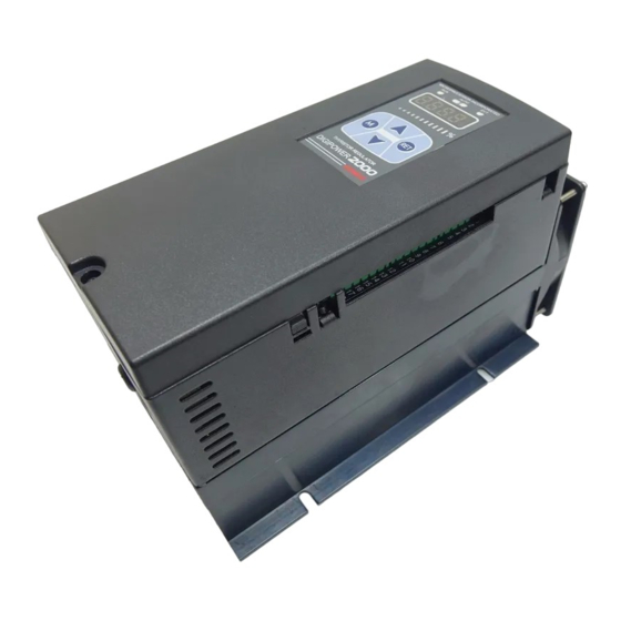
- Page 9 Series Part descriptions ① RUN lamp: Turns ON in RUN, turns OFF in STOP ① ② ③ ④ ① ② ③ ② AUTO lamp: Turns ON in AUTO, turns OFF in MANUAL ③ EVT lamp : Turns ON in Digital Input (DI-1 to 3) ON, fl ashes in alarm output ⑤...
- Page 10 Digital Thyristor Unit Functions A. Recorder ST-T ST-T SLOP SLOP ■ Soft Start [ ■ Output slope setting [ B. Indicator When controlling the load which has inrush current This function is to set output changed ratio by control input (platinum, molybdenum, tungsten, infrared lamp, etc) from 0.00 to 1.00 range.
- Page 11 Series UP-T UP-T DN-T DN-T ■ SLOW UP / SLOW DOWN [ ■ DI(Digital Input) It is same purpose as soft start function. Soft start starts Below functions are available by terminal input. only one time at fi rst but slow up/slow down function start Digital input has fi...
- Page 12 Digital Thyristor Unit HOLD ■ Proportional and integral constant set of ● HOLD [ A. Recorder feedback control After selecting HOLD function and digital input is Proportional Integral Control: ON(close), output and display value of this unit is B. Indicator hold.
- Page 13 Series SPAN SPAN H-BK H-BK ■ Input slope correction [ ■ Heater break alarm [ The principle of heater break alarm is load recognition function. It compensates the gain of the measured 100% input for It measures load resistance and when load resistance value is actual 100% input value.
- Page 14 Digital Thyristor Unit Monitoring mode A. Recorder Monitoring mode can monitor measured several physical quantities of this unit, not set parameters. B. Indicator ■ 1-phase C. Converter ※ 1. : Press any key among mode ※ To return RUN mode, press the key at any parameter, or not to operate any keys Press D.
- Page 15 Series Parameter mode ※ 1. : Press any key among ■ Operating Mode [ ※ To return RUN mode, press the key at any parameter, or not to operate any keys in 30sec. ※ : This parameter may or may not appear, depending on the other parameter settings. mode Press for 3 sec.
-
Page 16: Table Of Contents
Digital Thyristor Unit ※ 1. : Press any key among ※ If there is no operation any keys in 30sec., it returns to RUN mode. ■ Setting Mode 1 A. Recorder ※ Press the key when entering ST-1 setting mode in any parameters, it moves to ST-1. mode Press the key once more, it returns to RUN mode. -
Page 17: Press Any Key Among
Series ※ 1. ■ Setting Mode 2 : Press any key among ※ If there is no operation any keys in 30sec., it returns to RUN mode. ※ Press the key when entering ST-2 setting mode in any parameters, it moves to ST-2. mode Press the key once more, it returns to RUN mode. -
Page 18: Recorder
Digital Thyristor Unit Factory default A. Recorder ■ Operating Mode B. Indicator Parameter Default Parameter Default Parameter Default Parameter Default ST-T 0000 B-UP 00)0 C-LM 11)0 00)0 C. Converter S-LM 11)0 UP-T 0003 00)0 00)0 D. Controller S-LT 0000 DN-T 0003 00)0 0150... - Page 19 Series Function code 16(0×10) = write multiple resisters ● Request (Master → Slave) 0×01 0×10 0×00 0×00 0×00 0×10 0×20 ×× ×× Number of Start add. CRC 16 Com- Number data Add. mand of byte High High High ● Response (Slave →...
- Page 20 Digital Thyristor Unit ■ Address mapping table A. Recorder Holding resisters [1-phase] Address Item Factor B. Indicator 40001(0000) Reference value * 0.1(1 to 1000) 40002(0001) Start Time 0 to 99 C. Converter 40003(0002) Start limit * 0.1(1 to 1000) 40004(0003) Soft Start Time 0 to 99 D.
- Page 21 Series ■ Address mapping table Holding resisters [3-phase] Address Item Parameter Factor 40001(0000) Reference value 0.0 to 100.0 (*0.1) 40002(0001) Soft start time ST-T 0 to 100 (*1) 40003(0002) Start limit S-LM 0.0 to 110.0 (*0.1) 40004(0003) Start limit time S-LT 0 to 100 (*1) 40005(0004)
Need help?
Do you have a question about the DPU Series and is the answer not in the manual?
Questions and answers