Table of Contents
Advertisement
Quick Links
Advertisement
Chapters
Table of Contents

Related Manuals for Interpack ET xtreme Series

Summary of Contents for Interpack ET xtreme Series
- Page 1 ® ET xtreme Standard LD Tape Head Serial Numbers UH232T, UH432T...
-
Page 3: Table Of Contents
ABLE OF ONTENTS Section 1 T able Of Contents - -------------------------------------------- 3 H H H T U T U T U U U U T T T H H H Section 2 T echnical Assistance - ---------------------------------------- 4 H H H T U T U T U U U U T T T H H H Section 3 W arranty... -
Page 4: Technical Assistance
Head’s model number and serial number on hand. This information can be found on the label affixed to the Cover Frame of the Tape Head. Interpack Technical Support is available during normal business hours 8:30 a.m. to 5:00 p.m. (Eastern Time). -
Page 5: Warranty
Intertape sells its Interpack Tape Heads, Case Tapers and Case Erectors with the following warranties: ®... -
Page 6: Description Of Tape Head
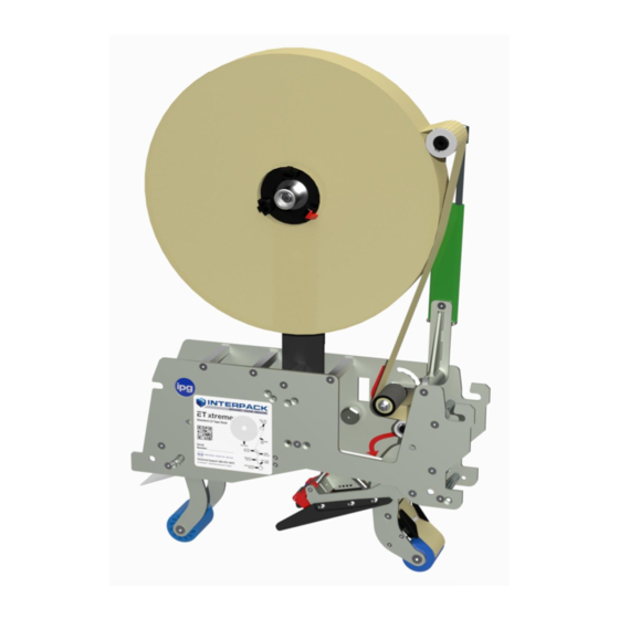
ESCRIPTION OF Figure 4-1 ® The Intertape ET xtreme Family of Tape Heads are designed to apply Intertape brand pressure sensitive carton sealing tape to the top and bottom center seam of regular slotted corrugated cartons. ® The ET xtreme LD tape heads were conceived to adapt to Loveshaw Little David case sealers. -
Page 7: Safety Issues
AFETY SSUES There is a safety label used on all Interpack Tape Heads. This label is placed on the Tape Head knife guard to warn operators and service personnel of the sharp cutting edge of the blade. Please read the label and the following safety precautions before using the Tape Head. - Page 8 AFETY SSUES The illustrated label shown in Figure 5-1 is attached to the Knife Guard. The label warns operators and service personnel of the very sharp blade. The guard shall only be removed when the torsion spring or the guard itself are being replaced. Should the tape head be operated without blade guard, user voids all warranty implied, the manufacturer bears no...
- Page 9 AFETY SSUES The illustrated label shown in Figure 5-4 is attached to the operator side plate of each tape head. The label provides operators and service personnel the proper method of threading a new roll of tape through the tape head. More detailed information is provided in the “Set Up Procedures”...
-
Page 10: Specifications
PECIFICATIONS T ape Head Dimensions U U U Figure 6-1... -
Page 11: Tape Head Components
PECIFICATIONS U U U Tape Head Components Figure 6-2... -
Page 12: Operating Conditions
PECIFICATIONS U U U Operating Conditions Use in a dry, relatively clean environment at 40º to 105º F (5º to 40º C) with clean, dry cartons. ® Note: The ET xtreme Standard Tape Head CAN be washed down with mild Detergent (soap). -
Page 13: I Nstallation In Other Machinery
Verify the case sizes which will be processed through the case sealer. Installing ® Interpack ET xtreme LD tape heads to process very short cases may cause the tape heads to collide with each other. -
Page 14: S Et Up Procedures
ROCEDURES R eceiving and Handling U U U All contents must be verified upon reception. The following items are included with each tape head. UH 232T UH 432T ESCRIPTION 2” W 3” W Main Tape Head assembly SS Main spring (part no. UPH1091) SS Ext. -
Page 15: Mounting Adapters
ROCEDURES ARNING URN OFF ELECTRICAL POWER SUPPLY AND DISCONNECT THE POWER CORD FROM THE ELECTRICAL SUPPLY BEFORE BEGINNING TO WORK ON THE EADS OR TO LOAD TAPE POWER CORDS ARE NOT DISCONNECTED SEVERE INJURY TO PERSONNEL COULD RESULT M ounting Adapters U U U ®... -
Page 16: T Ape Loading
ROCEDURES T ape Loading U U U ® The ET xtreme is designed to accommodate 2-inch (48mm) wide tape rolls, while the ET ® xtreme /3" accommodates 3-inch (72mm) wide rolls. 1. Place the tape head onto a sturdy, flat surface. 2. -
Page 17: T Ape Threading
ROCEDURES ARNING HE KNIFE CONTAINED IN THE EAD IS EXTREMELY SHARP SE CAUTION WHEN REMOVING THE BLADE GUARD AND THREADING THE TAPE TO AVOID PERSONNEL INJURY Tape Threading Preparation Figure 7-5 Threading the tape in the Tape Head does not require any special tools. Pull approximately twelve (12) inches of tape from the roll and fold in half lengthwise, adhesive side to adhesive side. - Page 18 ROCEDURES Adhesive Side Clutch Roller Knurled Rollers Guide Roller Application Roller Figure 7-7 Figure 7-6 Refer to Figures 7-6 & 7-7 for visual assistance of the following tape threading. 1. First thread the tape tail over the Peel Off Roller. 2.
-
Page 19: Tape Centering
ROCEDURES T ape Centering U U U If the tape is not centered as it travels through the tape shoe guide, the tape mandrel can be adjusted in or out to correct this. JAM NUT Loosen the M18 inverse jam nut on the rear of the mandrel as shown in Figure 7-8. - Page 20 ROCEDURES C entring 36mm(1 ½”) & 60mm(2 ½”) Tapes U U U If the tape is not a standard size, the tape mandrel hub will need a Spacer Ring to center the tape. Spacer Ring part # is UPH7435. Use the Spacer rings for the 36mm(1 ½”) tape on a 2” mandrel hub and the 60mm(2 ½”) tape on a 3”...
-
Page 21: T Ape Leg Length Adjustment
ROCEDURES T ape Leg Length Adjustment U U U For maximum sealing, the tape leg length has been factory set at 3 inches (76 mm). However, the tape leg length can be shortened. Front Tape Leg To adjust the tape leg length on the front panel of the box, refer to Figure 7-12 of the clutch assembly. -
Page 22: One Way Clutched Roller Adjustment
ROCEDURES Clutch Roller Adjustment The one-way clutch roller assures that the tape does not go backwards any time during dispensing, further more it is a tool in achieving correct front tape leg length. Different quality tapes have different adhesives and release coats. This has an effect on the dispensing, e.g. - Page 23 ROCEDURES Option 2: To change the rollers’ pressure one can move the spring retainers position on the cover frame. Move the M5 FHCS towards the front of the tape head to increase the pressure or towards M5 FHCS FRONT OF T.H. the rear to decrease the pressure.
- Page 24 ROCEDURES Knife Arm Spring Adjustment 1. To increase the force, using a 10mm open end wrench, turn the 6mm nylon lock nut clockwise until desired pressure achieved. 2. To decrease the force, using a 10mm open end wrench turn the nylon lock nut counter clockwise, so that the pressure on top flaps is reduced, but it stil cuts the tape.
-
Page 25: Troubleshooting
However, should a problem occur, we recommend that you consult the following table. If the problem you encounter is not discussed in this table, call Interpack Technical Support. (see page 2 of this document). ROUBLE... - Page 26 ROUBLESHOOTING ONTINUED ROUBLE OSSIBLE AUSES OLUTIONS Generally, too much tension on the application of the tape. Follow steps below. Applying urethane rollers, Remove any adhesive build up delrin guide rollers, knurled with silicon spray. Disassemble metal rollers should spin any non free spinning rollers and freely.
- Page 27 ROUBLESHOOTING ONTINUED ROUBLE OSSIBLE AUSES OLUTIONS Check for proper tape threading against threading diagram on side plate of tape head. Front tape leg too long. Tape threaded incorrectly. Tighten clutch roller a tad. Tape leg length misadjusted. Re-set front tape leg length. Follow corrective action in “Tape Generally, too much tension Flagging”...
-
Page 28: Recommended Spare Parts List
ECOMMENDED PARE ARTS We recommend that you stock the following spare parts. These parts are contained in the “spare parts kit” indicated below. The components of the spare parts kits are also referenced should individual components need to be ordered. Standard 2”... - Page 29 ECOMMENDED PARE ARTS Standard 3” Wide Spare Parts Kit UH 1011 ® ET xtreme Parts Contained in UH 1011 Spare Parts Kit ODEL UMBER ESCRIPTION UMBER UANTITY Front Roller 3’’ UPH1449 Dual Wiper Tabs 3” UPH4895 Ext. spring, light UPH0999 Ext.
-
Page 30: Preventive Maintenance
REVENTIVE AINTENANCE ARNING URN OFF ELECTRICAL POWER SUPPLY AND DISCONNECT THE POWER CORD FROM THE ELECTRICAL SUPPLY BEFORE BEGINNING TO WORK ON THE EADS OR TO LOAD TAPE POWER CORDS ARE NOT DISCONNECTED SEVERE INJURY TO PERSONNEL COULD RESULT ® The ET xtreme has been designed and manufactured with the finest components to provide long, trouble free performance. -
Page 31: O Iler Pad Lubrication
REVENTIVE AINTENANCE L ubrication U U U ® The ET xtreme components ship from the factory permanently lubricated. No additional lubrication is necessary, however, a small amount of lightweight oil applied to rotating and pivot points will extend the life of the tape head and assure maximum performance. There is, however, a felt pad on the blade guard which can serve as an oiler pad to help clean the blade should adhesive accumulate. -
Page 32: U Rethane Tacking Roller Replacement
REVENTIVE AINTENANCE A pplication Roller Replacement U U U These blue rollers are wear items and should be inspected regularly and replaced if necessary. Front & Rear Urethane Roller Replacement M6 –SCREW Removing The Urethane Roller 1. Using two Allen keys, remove the M6 screws. 2. -
Page 33: Spring Replacements
REVENTIVE AINTENANCE S pring Replacements U U U ® There are three springs on the ET xtreme . These springs are wear items and should be inspected regularly and replaced if necessary. Below are instructions for replacing the two most common springs. Main Spring Replacement 1. - Page 34 REVENTIVE AINTENANCE Knife Arm Spring Replacement If the compression spring breaks, the sequence to change it is as follows. 1. Remove the snap ring attached to the knife arm assembly. (Wear safety glasses while working with retaining rings). Snap Ring Figure 10-6 2.
- Page 35 REVENTIVE AINTENANCE 4. Press the spring barrel against the spring mandrel until it is ready to slide back on the short shaft. See Figure 10-9. Move the whole sub assembly back to its original position. Figure 10-9 5. Reinsert retaining ring to the grooves. Should the 10 mm retaining ring get damaged replace it with a new one.
- Page 36 REVENTIVE AINTENANCE Knife Guard Spring Replacement M5 BHCS As a precaution, remove the cutter blade to avoid injury. BLADE Figure 10-11 FRONT ROLLER Remove the cross shaft NOTE: These screws are secured with 2mm Hex. Key Loctite and may require applied heat prior to removal.
- Page 37 REVENTIVE AINTENANCE Carefully slide out the shaft from the end of the shaft that contains the remaining flathead screw. Figure 10-13 Remove the broken spring. Figure 10-14...
- Page 38 REVENTIVE AINTENANCE Behind The Cutter Blade Mounting To properly position the new knife spring Position the new knife spring as shown in Figure 10-15. Note which leg of the spring should lie behind the cutter blade mounting plate. Note that the looped leg shall wrap around the blade guard.
- Page 39 REVENTIVE AINTENANCE To Complete The Installation: Apply some purple Loctite (222) to the threads of the M3 screw and fasten to the end of the cross shaft. Tighten using two 2mm hexagonal keys as shown in Figure 10-17. The shaft should not vacillate in the mounting holes. Rotate the knife guard to make sure there is no binding.
-
Page 40: W Ipe Down Brush Replacement
REVENTIVE AINTENANCE W ipe Down Tap Replacement U U U This wiper tab assists in wiping down the top center seam of the case. While the blue tucking rollers perform much of the wipe down, the wipe down tab enhances the wipe down as it presses the adhesive into the corrugated fiber. -
Page 41: Schedule Of Preventive Maintenance
CHEDULE REVENTIVE AINTENANCE Frequency Item Action Required Material Weekly Monthly Quarterly Blade Guard Oiler Pad Lubricate Lightweight oil Hardware Re-tighten any loose hardware Replace any missing hardware Cutter Blade Inspect for wear Clean Solvent Cleaner Mandrel Assembly Disassemble & Observe Mandrel Friction Washer Clean Solvent Cleaner Mandrel Metal Washer None... -
Page 42: A Ppendix A-Illustrations And Parts Lists
A – I & P PPENDIX LLUSTRATIONS ARTS ISTS Tape Head Sub Assemblies ................... 44 Main Frame Assembly ....................46 Cover Frame Assembly ....................48 Front Arm Assembly....................... 50 Guide Roller ........................52 Tape Shoe Assembly ......................54 Front Roller ........................56 Rear Arm Assembly ...................... - Page 43 THIS PAGE INTENTIONALLY LEFT BLANK...
- Page 47 USH7064 USH7061 ITEM PART # DESCRIPTION 2"/QTY. 3"/QTY. UPH8205 MAIN FRAME LD UPH4040 SPACER BAR UPH1367 SPACER BAR UPH1387 SHAFT 10mm Dia. UPH1363 SHAFT 10mm Dia. UPH1423 SHAFT 12mm Dia. W/ SNAP RING UPH1422 SHAFT 12mm Dia. UPH1416 SHAFT 12mm Dia. W/ SNAP RING UPH1364 SHAFT 12mm Dia.
-
Page 51: Front Arm Assembly
USH1120 USH1119 ITEM PART # DESCRIPTION 2"/QTY. 3"/QTY. UAH0181 FRONT ARM 3" UAH0180 FRONT ARM 2" UPH1437 LIMIT BLOCK UPH1436 LIMIT BLOCK UPH1473 SLEEVE TUBING UPH4890 COMPRESSION SPRING UPH4890 COMPRESSION SPRING UF6425 SS FHCS M3-0.5 x 30mm UAH0209 TAPE SHOE ASS'Y 3" UAH0208 TAPE SHOE ASS'Y 2"... -
Page 53: Guide Roller
UAH0182 UAH0183 ITEM PART # DESCRIPTION 2"/QTY. 3"/QTY. UPH4925 GUIDE ROLLER UPH4926 COMPRESSION SPRING UPH4924 GUIDE ROLLER... -
Page 55: Tape Shoe Assembly
UAH0208 UAH0209 ITEM PART # DESCRIPTION 2" / QTY. 3" / QTY. UPH1434 TAPE SHOE 2" UPH1435 TAPE SHOE 3" UPH1438 STIFFENER BLOCK UF6350 SS FHCS M3-0.5 x 8 mm UPH7010 SS COMPRESSION SPRING UPH1510 FINGER... - Page 57 UAH0222 UAH0223 ITEM PART # DESCRIPTION 2"/QTY. 3"/QTY. UPH1439 ROLLER CORE UPH1440 ROLLER CORE UPH8143 SS COMPRESSION SPRING UF6402 F.W. PTFE, 12.5 x 17.5 x 0.5 mm UPH1448 FRONT ROLLER UPH1449 FRONT ROLLER UF4401 DISC SPRING 12.2 id - 21 od UF6335 F.W.
- Page 61 USH4133 ITEM PART # DESCRIPTION QTY. UPH4802 LINK ROD UPH4889 ROD END BEARING, 8mm UPH4801 ROD EYE SUPPORT UF3735 SS HNR M8-1.25 UF5608 SPECIAL WASHER UF6337 F.W. PTFE, 12.5 x 20 x 0.29 mm UF5614 WASHER PTFE 13 x 8.5 x 0.25...
- Page 63 USH1122 USH1123 ITEM PART # DESCRIPTION 2" / QTY. 3" / QTY. UAH0176 KNIFE ARM WITH BUSHINGS UAH0177 KNIFE ARM WITH BUSHINGS UAH0206 KNIFE GUARD 2" UAH0207 KNIFE GUARD 3" UPH9175 SHAFT, BLADE GUARD UPH9178 SHAFT, BLADE GUARD UPH4930 KNIFE AEM EXTENSION LEFT UPH4931 KNIFE ARM EXTENSION RIGHT UPH0193...
-
Page 65: Clutch Roller
USH1124 USH1125 ITEM PART # DESCRIPTION 2" / QTY. 3" / QTY. UAH0212 CLUTCH ROLLER UAH0213 CLUTCH ROLLER UPH1391 CLUTCH BRACKET UPH1452 GUIDE ROLLER UPH1453 GUIDE ROLLER UPH1454 SHAFT, 10mm UPH1455 SHAFT, 10mm UPH7077 CLUTCH SHAFT UPH7078 CLUTCH SHAFT UF3261 SS FHCS M6 -1 x 16 mm UF3275 SS FHCS M6 - 1 x 25mm... - Page 66 Standard Tape Head Mirror Tape Head...
- Page 67 UAH0212 UAH0213 UAH0226 UAH0227 ITEM PART # DESCRIPTION 2" /QTY. 3"/QTY. 2"mir./QTY. 3"mir./QTY. UPH8139 CLUTCH ROLLER UPH8140 CLUTCH ROLLER UPH1034 BEARING 12 x 14 x 12 LG SS UPH4857 ONE WAY BEARING, STAINLESS...
-
Page 69: Mandrel Assembly
USH1126 USH1127 USH1192 USH1193 ITEM PART # DESCRIPTION 2"/QTY. 3"/QTY. 2" Mir./QTY. 3" Mir./QTY. UAH0224 MANDREL ARM SUB ASS'Y UAH0225 MANDREL ARM SUB ASS'Y MIRROR UAH0178 MANDREL ASSEMBLY UAH0179 MANDREL ASSEMBLY UPH7004 SS HEX SOCKET PLUG UPH7687 SHAFT, MANDREL UPH7688 SHAFT, MANDREL UPH1006 SS MANDREL FRICTION WASHER... -
Page 71: Mandrel Hub
UAH0224 UAH0225 ITEM PART # DESCRIPTION QTY. Mir./QTY. UPH1459 MANDREL HUB UPH4808 MANDREL ARM UPH8150 MANDREL ARM MIRROR UF5904 SS FHCS M5-0.8 x 20mm... - Page 75 USH1057 USH1058 USH1129 ITEM PART # DESCRIPTION QTY. QTY. QTY. UAH0150 SPRING MANDREL V2 UAH0151 SPRING MANDREL V2 SS UPH7678 SPRING GUIDE V2 UPH8111 SPRING BARREL V2 UPH8123 SPRING BARREL V2 UPH4665 COMP. SPRING 13.7 O.D. 1.7 W.D. 50.8 LONG UPH7427 COMP.
- Page 77 USH1111 USH1112 USH1194 USH1195 ITEM PART # DESCRIPTION 2"/QTY. 3"/QTY. 2" Mir./QTY. 3" Mir./QTY. UPH1348 PEEL OFF ARM UPH1349 PEEL-OFF SLIDING ROD UPH1350 PEEL-OFF BLOCK UPH1346 PEEL-OFF BASE UPH1347 PEEL-OFF BASE UF6340 SS FW M5 UF7011 SS BHCS M5-0.8 X 12mm UF3169 SS SHCS M5-0.8 x 16mm UF7021...
- Page 78 No Tape Options are available...
- Page 79 ITEM PART # DESCRIPTION QTY. UPM7328 PHOTOELECTRIC SENSOR PNP UPM7329 PHOTOELECTRIC SENSOR NPN...
- Page 80 Low Tape Options are available...
- Page 81 ITEM PART # DESCRIPTION QTY. UPH8169 PHOTOELECTRIC SENSOR PNP UPH8144 PHOTOELECTRIC SENSOR NPN UF4518 SS BHCS M3 - 0.5 X 6...
Need help?
Do you have a question about the ET xtreme Series and is the answer not in the manual?
Questions and answers