Sign In
Upload
Download
Table of Contents
Contents
Add to my manuals
Delete from my manuals
Share
URL of this page:
HTML Link:
Bookmark this page
Add
Manual will be automatically added to "My Manuals"
Print this page
×
Bookmark added
×
Added to my manuals
Manuals
Brands
horsch Manuals
Paint Sprayer
Leeb 6.280 PT
Operating instructions manual
horsch Leeb 6.280 PT Operating Instructions Manual
Hide thumbs
1
2
3
4
5
Table Of Contents
6
7
8
9
10
11
12
13
14
15
16
17
18
19
20
21
22
23
24
25
26
27
28
29
30
31
32
33
34
35
36
37
38
39
40
41
42
43
44
45
46
47
48
49
50
51
52
53
54
55
56
57
58
59
60
61
62
63
64
65
66
67
68
69
70
71
72
73
74
75
76
77
78
79
80
81
82
83
84
85
86
87
88
89
90
91
92
93
94
95
96
97
98
99
100
101
102
103
104
105
106
107
108
109
110
111
112
113
114
115
116
117
118
119
120
121
122
123
124
125
126
127
128
129
130
131
132
133
134
135
136
137
138
139
140
141
142
143
144
145
146
147
148
149
150
151
152
153
154
155
156
157
158
159
160
161
162
163
164
165
166
167
168
169
170
171
172
173
174
175
176
177
178
179
180
181
182
183
184
185
186
187
188
189
190
191
192
193
194
195
196
197
198
199
200
201
202
203
204
205
206
207
208
209
210
211
212
213
214
215
216
217
218
219
220
221
222
223
224
225
226
227
228
229
230
231
232
233
234
235
236
237
238
239
240
241
242
page
of
242
Go
/
242
Contents
Table of Contents
Bookmarks
Table of Contents
Table of Contents
Introduction
Foreword
Notes on Representation
Service
Warranty Claim Processing
Consequential Damage
Safety and Responsibility
Intended Use
Qualification of Personnel
Children in Danger
Personal Protective Outfit
Safety in Traffic
Safety in Operation
Crop Protection Agents and Liquid Fertiliser
Environmental Protection
Retrofitting and Conversions
Care and Maintenance
Danger Zone
Use on Hillside Locations
Safety Stickers
Commissioning
Delivery
Transport
Installation
Initial Commissioning of the Service Brake System
Assemble the Wheels
Technical Data Leeb 6.280 / 8.280 PT (Variant Emission Standard Stage 3A)
Technical Data Leeb 6.300/ 7.300 / 8.300 PT (Variant Emission Standard Stage 5)
Type Plate
Dimensions
Weight and Tyres
Construction
Overview
Hydraulics
Lighting
Instruction Stickers
Components Chassis
Engine
Engine Oil
Engine Coolant
Compressed Air Connection
Ribbed V-Belt
Fuel Tank
Fill up Fuel / Urea Solution
Exhaust Gas System Leeb 6.280 / 8.280 PT
Exhaust Gas System
Leeb 6.300 / 7.300 / 8.300 PT
Hydraulic Oil Tank
Steering
Brake System
Mechanical Release Mechanism of Parking Brake
Axles
Wheel Drive
Wheels and Tyres
Wheel Change
Lifting Device
Adjust the Track Width
Suspension
Mechanical Release Device Folding Boom Parallelogram
Mechanical Release Device Spraying Pump and Venting Device
Maintenance Access
Cooler Package
Air Filter
Air Conditioning System
Refrigerant
Dryer Cartridge
Pressure Switch
Condenser
Checking Refrigerant Condition and Filling Quantity
Windscreen Washing System
Compressed Air System
Electrics
Battery
Battery Main Switch
Three-Phase Alternator
Starter
Transport and Safety Container
Tool Storage
Cabin
Access Ladder
Cabin Door
Overview
Overview Roof Console
Overview Roof Console
Overview Roof Console / A-Pillar
Driver's Seat
Overview
Weight Adjustment
Height Adjustment
Horizontal Suspension
Longitudinal Adjustment
Seat Inclination Adjustment
Seat Depth Adjustment
Arm Rest
Armrest Inclination
Backrest Adjustment
Lumbar Support
Lateral Horizontal Suspension
Seat Heating / Ventilation
Stowage Bag
Seat Belt
Instructor's Seat
Steering Column
Steering Column Adjustment
Multi-Function Switch
Driving Information
Multi-Function Control Panel
Overview of Operator Functions
Drive Lever
Transport / Service Position
Travel Direction Switch
Air Conditioning / Heater
Switching on the Air Conditioner / Heater
Switching on the Climate Control System
Setting the Cabin Temperature
Manual Fan Speed Control
Activate ECON Mode
Drying Cabin Windows with REHEAT Mode
Display Outside Temperature
Change Temperature Unit
Adjusting the Air Flow of the Air Conditioner
Malfunction and Remedy Air Conditioning System
Error Code Table
Running the Air Conditioner
Operating Terminal
Machine Terminal
Ignition Switch
Foot Pedal
Emergency Exit
Open Door Completely
Open Door a Gap
Sun Visor
Cabin Lighting and Reading Lamp
Cooling Box
Storage Compartment
Camera System
Overview
Main Menu
Rear View Camera (Optional)
Wheel Camera (Optional)
Nozzle Camera (Optional)
Outside Mirror
Mirror Adjustment
Sockets
Central Electrical System, Top
Central Electrics (CE) Machine
Circulating Air Filter
Fresh Air Filter Category 2
Cabin Air Filters Category 4 (Optional)
Radio
On / off
Multi-Mode Buttons
Volume Knob
Station Scan
Save Radio Station
Playing Media Files
Software Menu
Bluetooth
Engine Operation
Before Starting the Motor
Requirements for Motor Start
Switch on Ignition
Start the Engine
Shut down the Engine
Travel Operation
General Notes
Forward / Reverse Driving
Forward Driving
Reverse Driving
Reverse Direction of Travel
Brakes
Parking Brake
Service Brake
Drive Slippage Control
Travel Modes
Road Operation
Field Mode
Cruise Control
Road / Field Travel
Towing
Remote Start / Jump Start
Machine Terminal
Operation
Road Operation
Field Mode
Construction
Overview
Components Attachment
Spraying Mixture Container
Access Steps
Maintenance Access
Dome
Fresh Water Tank
Hand Washing Tank
Spraying Pump
Piston Diaphragm Pump
Illuviation Valve
Agitator
Filter
Control Unit
Fittings
Ports
Filter
External Control Terminal
Folding Boom
Folding Variants
Boomcontrol
Transport Lock
Collision Protection
Spraying Line
Nozzle Body
Optional Equipment
GPS Receiver (Optional)
Edge and Border Nozzles
Nightlight (Optional)
Direct Filling (Optional)
Wind Meter (Optional)
Outside Cleaning (Optional)
N-Sensor Bracket (Optional)
Safety Package (Optional)
Fire Extinguisher (Optional)
Operation
Commissioning
Parking
Transport Position
Multi-Function Control Panel
Overview of the Operator Functions for Spraying
Folding the Folding Boom
Unfolding
Folding
Sectionbox (Optional)
Preparation for Spraying Operation
Preparing the Spraying Mixture
Calculating Filling / Refill Quantities
Fluid Circuit
Construction
Function
Filling with Water
Filling the Spraying Mixture Container through the Filling Port
Direct Filling / External Filling (Optional)
Filling Via the Dome
Filling the Fresh Water Tank through the Filling Port
Illuviation of Preparations
Illuviation Valve
Flushing in Liquid Preparations During Filling
Flushing in Liquid Preparations with Full or Partly Filled Spraying Mixture Container
Illuviation of Powdery Preparations and Carbonyl Diamide
Canister Cleaning
Spraying Operation
Folding Boom Control
Control and Regulation of Spraying Functions
Residual Quantities
Technical Residual Quantities
Draining off Technical Residual Quantities
Diluted Residual Quantity
Draining the Fresh Water Tank
Cleaning
Cleaning the Filters
CCS - Continuous Inside Cleaning (Continuous Cleaning System)
Cleaning with Drained Spraying Mixture Container
Cleaning with Filled Spraying Mixture Container
Folding Boom Cleaning with Air Valve (Optional)
Cleaning the Spraying Mixture Container
Outside Cleaning (Optional)
Care and Maintenance
Faults
Attachment Maintenance Overview
Calibrating the Flow Meter
Inspection of the Crop Protection Sprayer
Maintenance Overview Chassis
Fuels and Lubricants
Maintenance of the Hydraulic System
Inspection Criteria for Hydraulic Hoses
Assembly and Disassembly of Hydraulic Hoses
Storage
At the End of the Season
Drain
Putting the Sprayer System into Winter Storage
Before the New Season
Waste Disposal
Appendix
Tightening Torque
HORSCH Leeb Metering Cup
Determining the Placing Quantity in L/Ha
Nozzle Selection and Control
Liquid Fertiliser Operation
Index
Advertisement
Quick Links
1
Service
Download this manual
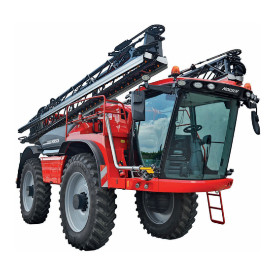
OPERATING INSTRUCTIONS
Leeb 6.280 / 8.280 PT
Leeb 6.300 / 7.300 / 8.300 PT
TRANSLATION OF THE ORIGINAL OPERATING INSTRUCTIONS
READ CAREFULLY PRIOR TO STARTING UP!
KEEP OPERATING INSTRUCTIONS IN A SAFE PLACE!
ART.:
60018524
ISSUE:
05/2020
Table of
Contents
Previous
Page
Next
Page
1
2
3
4
5
Advertisement
Table of Contents
Need help?
Do you have a question about the Leeb 6.280 PT and is the answer not in the manual?
Ask a question
Questions and answers
Related Manuals for horsch Leeb 6.280 PT
Farm Equipment horsch LEEB LT Operating Instructions Manual
Terminal (127 pages)
Paint Sprayer horsch Leeb 4 AX Operating Instructions Manual
(161 pages)
Paint Sprayer horsch Leeb 8.280 PT Operating Instructions Manual
(242 pages)
Paint Sprayer horsch LEEB PT 280 Operating Instructions Manual
(218 pages)
This manual is also suitable for:
Leeb 8.280 pt
Leeb 6.300 pt
Leeb 7.300 pt
Leeb 8.300 pt
Table of Contents
Print
Rename the bookmark
Delete bookmark?
Delete from my manuals?
Login
Sign In
OR
Sign in with Facebook
Sign in with Google
Upload manual
Upload from disk
Upload from URL


Need help?
Do you have a question about the Leeb 6.280 PT and is the answer not in the manual?
Questions and answers