
Related Manuals for Wittenstein cyber motor cyber dynamic 17

Summary of Contents for Wittenstein cyber motor cyber dynamic 17
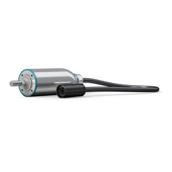
- Page 1 ® cyber dynamic line Rotating / linear electrical machine Operating Manual AC: 50014370 5022-D029179 Revision: 04...
- Page 2 Subject to technical and content changes without notice. Questa documentazione è protetta dai diritti d'autore. WITTENSTEIN cyber motor GmbH si riserva tutti i diritti, anche quelli relativi alla riproduzione fotomeccanica, alla riproduzione e alla diffusione, anche parziali, eseguite secondo processi particolari (quali ad es. l'elaborazione di dati, il supporto dati e le reti di dati).
- Page 3 D-97999 Igersheim Tel.: +49 7931 493-15900 Fax: +49 7931 493-10903 E-mail: service@wittenstein-cyber-motor.de This operating manual may be obtained from WITTENSTEIN cyber motor GmbH by specifying article number 50014370. Alternatively, it is available to download at: http://wittenstein-cyber-motor.de Revision: 04 5022-D029179 en-1...
-
Page 4: Table Of Contents
® cyber dynamic line Contents About this manual ....................4 1.1 Signal words ......................4 1.2 Safety symbols.....................5 1.3 Design of the safety instructions ................5 1.4 Information symbols .....................5 Safety........................6 2.1 EC/EU Directive ....................6 2.2 Dangers .......................6 2.3 Personnel ......................6 2.4 Intended use ......................6 2.5 Guarantee and liability ..................6 2.6 Other applicable documents ................6 2.7 General safety instructions ..................7... - Page 5 ® cyber dynamic line Appendix ......................23 9.1 Tightening torques for common thread sizes in general mechanical engineering ................23 10 Appendix II ......................24 10.1Attachment recommendation ................24 10.1.1Attachment recommendation: Standard (IP54) ..........24 10.1.2Attachment recommendation: Inox Design (IP66/67) ........25 10.1.3Attachment recommendation: Hygienic Design (IP69K).......26 Revision: 04 5022-D029179 en-3...
-
Page 6: About This Manual
® About this manual cyber dynamic line 1.1 Signal words About this manual This manual contains information which is necessary for the safe use of the electromagnetic ® actuator of the cyber dynamic line. The electromagnetic actuator (including motors, motor- gearbox combinations and linear actuators) will be referred to simply as the motor in the following. -
Page 7: Safety Symbols
® cyber dynamic line About this manual 1.2 Safety symbols Safety symbols The following safety symbols are used to indicate possible hazards, prohibitions, and important information: General danger Hot surface Suspended loads Danger of being pulled in Magnetic field Information Electric voltage Electrostatic discharge sensitive component... -
Page 8: Safety
- Operation of the motor with defective protection devices and mechanisms - Operation of a severely soiled motor - Changes or modifications that have been realized without the written approval of WITTENSTEIN cyber motor GmbH Other applicable documents You have already received the following documents for your specific motor: - Dimensional drawing (5007–…) -
Page 9: General Safety Instructions
(especially with rotary kit motors or the primary and secondary parts of linear motors), you are prohibited from approaching these motor parts. If there are concerns, contact the manufacturer of the active medical implants or consult WITTENSTEIN cyber motor GmbH. Revision: 04 5022-D029179 en-7... - Page 10 ® Safety cyber dynamic line 2.7 General safety instructions Objects flung out by moving components can cause serious injuries and death. Remove objects and tools from the motor prior to starting it up. Moving components on the motor can pull in or crush parts of the body and cause serious injuries and even death.
- Page 11 ® cyber dynamic line Safety 2.7 General safety instructions During the mechanical assembly and maintenance of kit motors (rotary motors without housings or linearly moving primary and secondary parts), the attractive forces of the permanent magnets can cause severe crushing injuries and damage to the motor or the application.
-
Page 12: Description Of The Motor
® Description of the motor cyber dynamic line 3.1 General information Description of the motor General information All motors are brushless electrical machines and conform to the applicable standards and regulations, in particular: - DIN EN 60034–1:2011 (VDE 0530) Rotating electrical machinery The motors are therefore suitable for use in machines and systems in accordance with DIN EN 60204–1:2007 "(VDE 0113) Safety of Machinery –... -
Page 13: Mrxx Identification Plate (Motor)
® cyber dynamic line Description of the motor 3.2 Name plate 3.2.1 MRxx identification plate (motor) Designation Product designation E FG Type key Material number Insulation class Protection class Calendar week and year of production Serial number CE marking I J K L Service Portal Code Data matrix code (DMC) Intermediate voltage U... -
Page 14: Alxx Identification Plate (Linear Actuator)
® Description of the motor cyber dynamic line 3.3 Performance data 3.2.3 ALxx identification plate (linear actuator) Designation Product designation E FG Type key Material number Insulation class Protection class Calendar week and year of production Serial number CE marking I J K L Service Portal Code Data matrix code (DMC) -
Page 15: Transport And Storage
Check the completeness of the delivery against the delivery note. Missing parts or damage must be notified immediately in writing to the carrier, the insurance company, or WITTENSTEIN cyber motor GmbH. Packaging The motor is delivered packed in foil and cardboard boxes. -
Page 16: Assembly
® Assembly cyber dynamic line 5.1 Preparations Assembly Read the general safety instructions before beginning work (see Chapter 2.7 "General safety instructions"). Preparations Pressurized air may damage the seals of the motor. Do not use pressurized air for cleaning the motor. ... -
Page 17: Attaching Motor To A Machine
® cyber dynamic line Assembly 5.2 Attaching motor to a machine Attaching motor to a machine Observe the safety and processing instructions for the threadlocker to be used. Installation examples for reaching specific IP protection classes 10 "Appendix II". Coat the fastening screws with a threadlocker. -
Page 18: Installing Electrical Connections
® Assembly cyber dynamic line 5.4 Installing electrical connections Installing electrical connections Electrically live components may result in electric shocks if touched and can cause serious injuries and even death. Observe the five safety rules of electrical engineering before starting ... -
Page 19: Startup And Operation
® cyber dynamic line Startup and operation 6.1 Safety information and environmental conditi- Startup and operation Safety information and environmental conditions Read the general safety instructions before beginning work (see Chapter 2.7 "General safety instructions"). Improper use can cause damage to the motor. Ensure that the limit values in the following sub-chapters are observed. -
Page 20: Running In The Holding Brake
® Startup and operation cyber dynamic line 6.2 Holding brake - In the case of a malfunction, the operating principle when using the holding brake to shut down a moving axle (emergency stop) is a dynamic friction with the friction coefficient µ . -
Page 21: Testing The Holding Brake Regularly
® cyber dynamic line Startup and operation 6.3 Data for the electrical startup Calculate the power of the motor I required to achieve the holding torque M with the torque constant, and limit the maximum current of the regulating device to this value. Apply current to the motor with the holding brake applied, gradually increasing the current to ... -
Page 22: Operation
® Startup and operation cyber dynamic line 6.4 Operation Moving the motor during the switch-on process of the encoder system can lead to malfunctions. When commissioning the motor, make sure that the motor is not moved during the switch-on process of the encoder system. The switch-on process is completed as soon as the encoder system ... -
Page 23: Maintenance And Disposal
® cyber dynamic line Maintenance and disposal 7.1 Maintenance Maintenance and disposal Read the general safety instructions before beginning work (see Chapter 2.7 "General safety instructions"). Maintenance 7.1.1 Cleaning Clean the motor with a grease-dissolving, non-aggressive detergent. 7.1.2 Checking the holding brake The motor can be optionally equipped with a holding brake. -
Page 24: Malfunctions
® Malfunctions cyber dynamic line Malfunctions Changed operational behavior can be an indication of existing damage to the motor or cause damage to the motor. Do not put the motor back into operation until the cause of the malfunction has been rectified. Fault Possible cause Solution... -
Page 25: Appendix
® cyber dynamic line Appendix 9.1 Tightening torques for common thread sizes in Appendix Tightening torques for common thread sizes in general mechanical engineering The specified tightening torques for headless screws and nuts are calculated values and are based on the following conditions: - Calculation according to VDI 2230 (edition 11/2015) - Friction value for thread and contact surfaces µ=0.10 - Utilization of the yield stress 90%... -
Page 26: Attachment Recommendation
As the specific installation situation at the customer site is not known, the following attachment recommendations are only to be regarded as examples. WITTENSTEIN cyber motor GmbH does not assume any liability for constructive integration by the customer. 10.1.1 Attachment recommendation: Standard (IP54) ®... -
Page 27: 2Attachment Recommendation: Inox Design (Ip66/67)
® cyber dynamic line Appendix II 1 Attachment recommendation 10.1.2 Attachment recommendation: Inox Design (IP66/67) ® By default, cyber dynamic line Inox Design features - protection class IP66/67 on the cable outlet side (B), - protection class IP20 on the customer outlet side (A). -
Page 28: 3Attachment Recommendation: Hygienic Design (Ip69K)
® Appendix II cyber dynamic line 1 Attachment recommendation 10.1.3 Attachment recommendation: Hygienic Design (IP69K) ® By default, cyber dynamic line Hygienic Design features - protection class IP69K on the cable outlet side (B), - protection class IP67 on the customer outlet side (A). - Page 29 ® cyber dynamic line Revision history Revision Date Comment Chapter 23.08.13 New version 26.02.15 Technical data, 3, 5, Tightening torques, 9.3, Layout 08.08.17 Safety, 3, 4, 5, 7, 8, 9 Technical data 06.05.20 Safety, 3, 4, 5, 6 Technical data, Identification plate Attachment recommendation...
Need help?
Do you have a question about the cyber dynamic 17 and is the answer not in the manual?
Questions and answers