Table of Contents
Advertisement
Quick Links
actiLib Kodiak 3407
Quick Start Guide
Document Purpose
This document provides a product overview and information to install and the initial setup
of the actiLib Kodiak 3407 Scalable Tape Library. The instruction is intended for trained
System Administrators and Users who need physical and functional knowledge of the
actiLib Kodiak 3407 library.
actidata Storage Systems GmbH - 07/12/2018
Advertisement
Table of Contents

Summary of Contents for Actidata actiLib Kodiak 3407
-
Page 1: Document Purpose
This document provides a product overview and information to install and the initial setup of the actiLib Kodiak 3407 Scalable Tape Library. The instruction is intended for trained System Administrators and Users who need physical and functional knowledge of the actiLib Kodiak 3407 library. - Page 2 Release Author Revision Change No. Description Date Verified by yyyy-mm-dd Timo Kühne 2018-06-06 Initial Revision / 42...
-
Page 3: Table Of Contents
Inhaltsverzeichnis Document Purpose ........................... 1 Introduction ..............................5 Document Purpose ........................... 5 General Warnings ............................6 Document Conventions: .......................... 6 General Product Warnings ........................6 Product Overview ............................10 Supported Library Configurations – Rackmount Installation ............10 Supported Module Configurations with Legacy Serial ADI Drive Sleds ........13 Supported Tape Drives .......................... - Page 4 Labeling Tape Cartridges ........................35 Write Protecting Tape Cartridges ....................36 Initial Setup of the Library........................37 Using the OCP ............................37 Using the RMI ............................37 Logging into the Library ........................38 Using the Initial Configuration Wizard on the OCP ................. 38 Get help................................
-
Page 5: Introduction
This document provides information to install, operate, upgrade, service and troubleshoot the actiLib Kodiak 3407 Scalable Tape Library. The instructions are intended for the trained System Administrators and trained Users who need physical and functional knowledge of the actiLib Kodiak 3407 library. WARNING •... -
Page 6: General Warnings
its approved agent. ▪ The tape library is repaired by anyone, including an approved agent, in a manner that is contrary to the maintenance or installation instructions supplied by the manufacturer. ▪ The manufacturer's serial number tag is removed. ▪ The tape library is damaged because of improper packaging on return. Warranty will become immediately void in the event of unauthorized repairs or modifications. - Page 7 Risque de choc électrique • Ne pas retirer le couvercle de l'alimentation. Aucune pièce réparable par l'utilisateur ne se trouve à l'intérieur à moins que celle-ci ne soit spécifiquement identifiée. • Confier toute réparation à un personnel qualifié. Danger MECHANICAL Risk of hand pinching, can trap hands, fingers and cause serious injury.
- Page 8 Poids du produit AVERTISSEMENT Risque de blessure Avant de soulever un module: ▪ Respectez les règles locales de santé et de sécurité au travail ainsi que les instructions concernant la manipulation du matériel. ▪ Retirez toutes les cartouches à bande pour réduire le poids ▪...
- Page 9 Ventilation – Placez le produit dans un endroit qui ▪ REMARQUE n'interfère pas avec une ventilation approprié. ▪ Chaleur – Placez le produit dans un endroit loin de sources de chaleur. ▪ Alimentation électrique – Veuillez ne brancher le produit qu’à...
-
Page 10: Product Overview
Supported Library Configurations – Rackmount Installation All actiLib Kodiak 3407 Libraries start with a Base Module. Up to 6 Expansion Modules can be added as needed to support customer requirements. The architecture has been designed to support a maximum of 3 Expansion Modules above and 3 Expansion Modules below. - Page 11 Module Quantity Supported Library Configurations 1 Module Library Base Module 2 Module Library Base Module 1 Expansion Module 3 Module Library Base Module 2 Expansion Modules 4 Module Library Base Module 3 Expansion Modules / 42...
- Page 12 Module Quantity Supported Library Configurations 5 Module Library Base Module 4 Expansion Modules 6 Module Library Base Module 5 Expansion Modules 7 Module Library Base Module 6 Expansion Modules / 42...
-
Page 13: Supported Module Configurations With Legacy Serial Adi Drive Sleds
Mixed drive generations and mixed interfaces are supported within a single library and within a single module. Listed below are the tape drives that have been implemented and qualified for use in actiLib Kodiak 3407. IBM LTO Drives HP LTO Drives... -
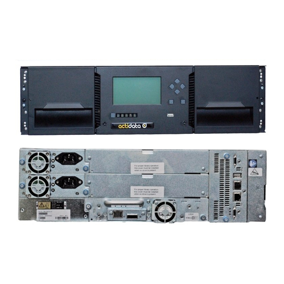
Page 14: Front Panel
Front Panel Left Magazine Emergency Release Access Hole Left Magazine Access Handle Power Button Base Module Only Unit Identification LED, Blue Base Module Only Ready LED, Green Base Module Only Clean LED, Amber Base Module Only Attention LED, Amber Base Module Only Error LED, Amber Base Module Only USB Port... -
Page 15: Rear Panel
Rear Panel Power Supply 1 Standard on Base Module Optional on Expansion Module Power Supply 2 Optional on Base Module Optional on Expansion Module Half-Height Tape Drive Bays Upper Expansion Module Connection Port USB Port Optional on Base Module Only Ethernet Port A Base Module Only Ethernet Port B... -
Page 16: Element Numbering
Element Numbering The library will generally display logical element numbering of modules, storage slots and tape drives starting with number one from the bottom up. Left Magazine Right Magazine, Mailslot Disabled Right Magazine, Mailslot Enabled / 42... -
Page 17: Installing The Library
Installing the Library Planning Installation • Choose a location for the library. See “Location Requirements”. • “SAS Plan the SAS or Fibre Channel configuration and obtain the necessary cables. See Requirements” or “Fibre Channel Configuration Configuration Requirements”. • For rack installations, plan the rack layout. See “Planning the Module and Rack Layout”. -
Page 18: Fibre Channel Configuration Requirements
drive uses one channel, so each HBA port can support up to four tape drives. You can use a cable with one connector on each end, but only one channel will be used. Supported speeds by drive generation are shown in the table below. Supported SAS Speeds LTO Generation Supported Speeds... -
Page 19: Planning Module And Rack Layout
Planning Module and Rack Layout If possible, install the Base Module in the middle of the rack to provide space for the permitted 3 Expansion Modules above and 3 Expansion Modules below. See 5.1 Supported Library Configurations for additional details. Internal IP Range Selection For internal communication between modules the tape library uses an Ethernet connection with an internal IP address range. -
Page 20: Host Preparation
Host Preparation Static Sensitive CAUTION Risk of damage to devices ▪ A discharge of static electricity damages static-sensitive devices or micro circuitry. ▪ Proper packaging and grounding techniques are necessary precautions to prevent damage. Électricité statique ATTENTION Risque d'endommager les périphériques par une décharge d’électrostatique. -
Page 21: Installation Precautions
Installation Precautions Product Weight WARNING Each actiLib Kodiak 3407 module weighs more than 20 kg (44 lbs) without drives or tapes and more than 35 kg (77 lbs) with 3 tape drives and 40 tapes. Risk of personal injury Before moving or lifting a module: ▪... -
Page 22: Unpacking Base Module And Expansion Modules
15° C (30° F) from where the module was stored, allow it to acclimate for at least 12 hours prior to unpacking. Unpacking a actiLib Kodiak 3407 Base Module or Expansion Module: 1. Before opening and removing a module from the box, inspect the container for shipping damage. - Page 23 7. Lift the cover front end by about 12 cm and pull gently forward to disengage from the pivot point at the unit center 8. Remove the insertion foam. 9. If you are installing a Base Module only without an Expansion Module install the top cover again on the Base Module 10.
-
Page 24: Identifying Library Module Components
Identifying Library Module Components If you have unpacked a Base Module, confirm that you have received the following components: 1. Base Module 2. Two Rack Rails 3. Accessory Kit One packet of rack mount hardware One North American Power Cord One European Power Cord If you have unpacked an Expansion Module, confirm that you have received the following components: 1. - Page 25 Lift the cover front end by about 12 cm Pull gently forward to disengage from the pivot point at the unit center 2. Install top cover on the Expansion Module that will be installed on the top of the library. Place the Expansion Module on a work table With the front of the top cover raised approximately 12 cm, engage the rear of the cover at the Expansion Module pivot point located at the back of the...
- Page 26 Install the library bottom cover plate to the an Expansion Module. Place the Base Module on a work table Lift the unit front end by about 16 cm (use unit rear as a pivot edge) Insert the bottom cover at the center Lift up the cover front edge until hard stop and it locks in at the unit front.
-
Page 27: Installing Modules In A Rack
Installing Modules in a Rack actiLib modules are easy to install in racks compliant to the EIA 310A Standard, when at least 1 meter deep. You need a #2 Phillips screwdriver for this process. To locate the rail locations when installing multiple modules: 1. - Page 28 1. Place the library at the front of the rack on the support angles of the sliding rails and push it into the rack to the back stop. 2. If you are installing multiple modules, verify that this module has been installed directly above or below its adjacent module and is contained within the correct 3U volume.
-
Page 29: Aligning And Connecting Modules
Aligning and Connecting Modules Skip this step if the library does not have Expansion Modules. Aligning the modules ensures that the robot can move freely between the modules. The library will not operate unless the alignment mechanism is in the locked position. 1. - Page 30 3. Verify that the lowest module in the library has its alignment mechanism in the unlocked position 4. From the front of the library, tighten the Philips screws on each of the modules to secure the modules to the rack. 5.
-
Page 31: Installing Tape Drives
Installing Tape Drives 1. Locate an appropriate vacant drive bay on the back of the library. 2. To assist in aligning the drive, only remove the drive bay covers for one drive at a time. Remove the face plate covering the drive bay by removing the screws holding it in place. Remove one drive bay cover to install one half-height tape drive. -
Page 32: Powering On The Library
Powering On the Library 1. Plug the power cables into the power connectors on each module and into power outlets. The library has dual redundant power supplies. To increase redundancy, plug NOTE each power cord into a different AC power circuit. 2. -
Page 33: Labeling Tape Cartridges
• LED flashing slowly: unlock operation in process • LED flashing quickly: mailslot or magazine is unlocked and can be removed Example: 3-module-library with mailslots enabled on the top 2 modules NOTE You can also open mailslots or magazines through the Operation > Open Mailslot or Operation >... -
Page 34: Bulk Loading Magazines
Bulk Loading Magazines 1. Press the button for more than 3 seconds. This will start the unlock operation for the magazine, indicated by the LED slowly flashing. 2. When the magazine is unlocked the LED starts quickly flashing 3. Pull out the magazine from the library. As soons as the magazine is pulled out, the LED switches OFF. •... -
Page 35: Tape Cartridges And Magazines
Tape Cartridges and Magazines This chapter explains which how to label and write-protect your tape cartridges. Careful labeling and handling of the tape cartridges will prolong the life of the tape cartridges and the library. Using and Maintaining Tape Cartridges CAUTION Do not degauss LTO data cartridges! These data cartridges are pre- recorded with a magnetic servo signal. -
Page 36: Write Protecting Tape Cartridges
IMPORTANT Misusing and misunderstanding bar code technology can result in backup and restore failures. Use only high quality labels. Self-printed labels are not recommended as they are often a source of barcode reading issues. LTO tape cartridges have a recessed area located on the face of the cartridge next to the write-protect switch. -
Page 37: Initial Setup Of The Library
Initial Setup of the Library The library provides two main interfaces: • Operator Control Panel (OCP) — With the OCP, you can monitor, configure, and control the library from the front panel. • Remote Management Interface (RMI) — With the RMI, you can monitor, configure, and control the library from a web browser. -
Page 38: Logging Into The Library
Check the online help in the RMI for additional information. The help pages are updated with firmware updates and often contain up-to-date technical details that might not be contained in this document. To access RMI help, click the ? icon on the right side of the RMI top banner. Logging into the Library To login to the library on the OCP: 1. - Page 39 NOTE On the very first power up of the library the user is prompted to walk through the Initial Configuration wizard. It is recommended to walk completely through the wizard and finish the wizard by pressing the Finish Button. Otherwise with every login on the OCP the user will be prompted again to walk through the wizard.
- Page 40 Table 2: Default Settings Parameter Default Setting Reset to Default? User Accounts User = user “User” User NOT reset PW = null User= administrator NOT reset Administrator login PW = adm001 User = service Service Login (requires admin pwd in NOT reset PW = ser001 addition to service pwd)
- Page 41 Default controller IP 10.144.4.1 NOT reset Magazines & Mailslots (I/O Station) Mailslots Disabled Magazines/Mailslots Allow user "User" Disbaled access Disabled (one underlying All deleted leaving a single partition Partitions partition) NTP/SNTP Setting Disabled NOT reset Date Blank or existing NOT reset Time Blank or existing NOT reset...
-
Page 42: Get Help
Automatic/Automatic NOT reset Odometer Enabled Get help The actiLib Kodiak 3407 Tape Library User and Service Guide will give you more details about • how to install, configure and use your Tape libraray • to Specifications of your interest actidata Storage Systems GmbH Wulfshofstr.
Need help?
Do you have a question about the actiLib Kodiak 3407 and is the answer not in the manual?
Questions and answers