
Summary of Contents for IntelliSAW IRM-48
- Page 1 IntelliSAW IRM-48 Reader INSTALLATION MANUAL Document: 910.00371.0001 Revision: Date: 14 July 2016 Page 1 of 28...
- Page 2 IntelliSAW IRM-48 Reader Copyright © 2016, IntelliSAW IntelliSAW reserves the right to make technical changes or modify the contents of this document without prior notice. IntelliSAW is not responsible for errors or possible lack of information in this document. IntelliSAW reserves all rights in this document and in the subject matter and illustrations contained therein.
- Page 3 IntelliSAW IRM-48 Reader MPORTANT NFORMATION This symbol identifies messages in this document related to safety. DANGER DANGER indicates an imminently hazardous situation, which, if not avoided, will result in death or serious injury. Failure to follow the instructions given will result in death or serious injury.
-
Page 4: Table Of Contents
IntelliSAW IRM-48 Reader ABLE OF ONTENTS Introducing the IRM-48 Reader ................... 6 Models ......................... 6 Instructions for Use ...................... 6 Product Overview ........................ 7 System Inputs and Outputs ..................7 Labeling ........................7 2.2.1 Serial ID Label ...................... 7 2.2.2 Compliance Label .................... - Page 5 IntelliSAW IRM-48 Reader Product Certifications ......................25 Compliance .........................25 Wireless Certifications ....................26 8.2.1 Telecommunication Compliance ................26 8.2.2 Approved Antennas .....................26 8.2.3 Federal Communications Commission (FCC) ............26 8.2.4 Industry Canada (IC) ....................27 Contact ..........................28 Installation Manual Page 5 of 28 IRM-48 Reader...
-
Page 6: Introducing The Irm-48 Reader
1.2 I NSTRUCTIONS FOR The IRM-48 Reader is intended for use in the measurement of Temperature, Humidity, Ambient Temperature, Partial Discharge and Surface Discharge of Low to Medium Voltage air insulated Electrical Equipment. Readers connect Air Interfaces through RF cables for wireless interrogation of SAW temperature sensors and Partial Discharge monitoring, while humidity and ambient temperature sensors are wired to the readers. -
Page 7: Product Overview
The Reader has two labels on the bottom of the unit, a Serial ID label and a compliance label, and one main product label on the top. 2.2.1 Serial ID Label The IRM-48 Serial ID label provides a model number and serial number for the reader. Figure 1: IRM-48 Model Number and Serial ID Label 2.2.2 Compliance Label The compliance label provides product certification information. -
Page 8: Product Label
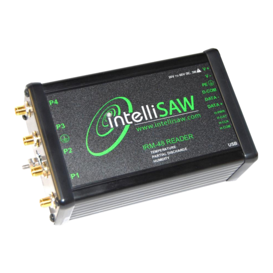
IntelliSAW IRM-48 Reader 2.2.3 Product Label The top product label provides guidance to the model type, product voltage and power ratings, and connector interfaces. Voltage and power ratings Model Identification Figure 3: Product top label Model identification boxes will be red if the option is available in the reader. -
Page 9: Usb Cable Connector
IntelliSAW IRM-48 Reader 2.3.1 USB Cable Connector Interface Name Description USB mini used for unit configuration 2.3.2 Power and Modbus RTU Connector Name Description Power In + Input power range from 24 to 60V DC. Power In - Input power range from 24 to 60V DC. -
Page 10: Humidity Sensor Connector
IntelliSAW IRM-48 Reader 2.3.4 Humidity Sensor Connector Name Description H-PWR Humidity Power Humidity Cable Power Input from Humidity Sensor H-DAT Humidity Data Humidity Cable DATA Input from Humidity Sensor H-CLK Humidity Clock Humidity Cable Clock Input from Humidity Sensor Humidity... -
Page 11: Installation
IntelliSAW IRM-48 Reader NSTALLATION IMPORTANT • The installation instructions are only for the Reader. IRM-48 • It is assumed an Air Interface Antenna, and Sensors have been installed and configured. WARNING INSTALLATION AND CONFIGURATION SHOULD BE PERFORMED ONLY BY PERSONNEL WHO ARE TECHNICALLY COMPETENT AND AUTHORIZED TO DO SO. -
Page 12: Dimensions
IntelliSAW IRM-48 Reader 3.2 D IMENSIONS The IRM-48 instrument has dimensions of 81 H × 142.5 W x 51.5 mm D (3.19 H × 5.61 W × 2.03 in D). Figure 5: IRM-48 Dimensions (in mm) 3.3 D OUNTING CAUTION ENSURE THE INSIDE OF THE PANEL IS WITHIN THE READER’S OPERATING... -
Page 13: Installation Location
7m of the Air Interface, the maximum length of the Air Interface Antenna RF cable. 3.3.2 Recommended Spacing It is recommended to allow up to 5 cm (2 in.) for the IRM-48 Reader connectors. It is best to have the USB connector easily accessible. Installation Manual... -
Page 14: Wiring
IntelliSAW IRM-48 Reader IRING WARNING SYSTEM WIRING SHOULD BE PERFORMED ONLY BY PERSONNEL WHO ARE TECHNICALLY COMPETENT AND AUTHORIZED TO DO SO. LOCAL REGULATIONS REGARDING ELECTRICAL INSTALLATION AND SAFETY MUST BE OBSERVED. Failure to follow the instructions given can result in death or serious injury WARNING TO AVOID ELECTRICAL SHOCK. -
Page 15: Power And Modbus Rtu Connections
Figure 9: Power and Modbus RTU Connections 4.1.1 Power The IRM-48 Reader operates at 48VDC nominal power, but can operate between 24 to 60V DC with a total power consumption of 3.5 W. The following block diagram outlines the recommended power wiring for the IRM-48 Reader with a 2-pole circuit breaker and AC/DC power supply. - Page 16 4.1.1.1 Local versus bussed DC power IntelliSAW recommends the use of a DC power supply in the same low-voltage compartment as the reader. This is the simplest and most flexible option. It is possible to run a DC power bus alongside the RS485 bus, however, this option requires careful consideration of the wire diameter.
-
Page 17: Communication Connections
Figure 11: RS485 Data Communication Bus Topology 4.2.1.1 Recommended Cabling IntelliSAW recommends the use of shielded cable for the RS485 wiring, providing at least one twisted pair, one single line, and a drain wire, although typical cable has two twisted pair. The twisted pair provides DATA+/- signals to each reader while the single line would be for D-COM, providing a low-impedance return for each reader. - Page 18 The RS485 bus data rate is dependent on the bus cable length and the number of readers on the bus. In industrial environments, slower data communication rates are generally more reliable; IntelliSAW recommends either 19200 baud or 9600 baud for the data rate. Bus length Bus cable length has an impact on the overall data rates which can be achieved.
-
Page 19: Humidity Sensor Connections
ENSOR ONNECTIONS The Humidity Sensor Connector is a 4 position male connector. The connector accepts 16-26 AWG wire. It is recommended that Ferrules be used for all terminating wires. The IntelliSAW Humidity sensor is shipped with a cable assembly. HUMIDITY... -
Page 20: Sensor Installation & System Configuration
YSTEM ONFIGURATION 5.1 S ENSOR NSTALLATION This manual does not cover specific sensor installation. Please reference the IntelliSAW Sensor Installation Manual for more detail. 5.2 S YSTEM ONFIGURATION The Reader requires system configuration for the associated installed temperature sensors, air interfaces, and humidity sensors. -
Page 21: System Integration
The IRM-48 Reader has one RS485 slave communication connection. The Reader can be connected to a CAM-4 unit or an existing SCADA, DCS, or historian system. All IRM-48 readers are slave devices polled by either a Master CAM-4 unit or SCADA system. -
Page 22: Modbus Registers
IntelliSAW IRM-48 Reader 6.2 M ODBUS EGISTERS Note: table items highlighted in blue are not yet implemented. REGISTER DESCRIPTION TYPE SCALE ERROR CODE temp 1 signed 16 -500 1675 0.1 C 0x8000 temp 2 signed 16 -500 1675 0.1 C... - Page 23 IntelliSAW IRM-48 Reader surface 1 unsigned 16 65534 10 "Q " 0xFFFF internal 1 unsigned 16 65534 10 "Q " 0xFFFF noise 2 unsigned 16 65534 10 "Q " 0xFFFF surface 2 unsigned 16 65534 10 "Q " 0xFFFF internal 2 unsigned 16 65534 10 "Q...
-
Page 24: Specifications
Up to 1.75 m (2.5 m with TPD air interface) ≤ 160 mSec RF Interrogation Time PARTIAL DISCHARGE Number of Channels Up to 4 IntelliSAW CAM Air Interfaces (TPD) Measurement Method Ultra-High Frequency (UHF) Selectable Bands (Center Frequency) 300MHz, 600MHz, or 1200MHz... -
Page 25: Product Certifications
IntelliSAW IRM-48 Reader RODUCT ERTIFICATIONS 8.1 C OMPLIANCE UL / cUL 61010-1 Safety Requirements for Electrical Equipment for Measurement, Registered Control, and Laboratory Use - Part 1 IEC61000-6-5 Level 4 substation EMC/EMI per IEC61000-4-x below IEC 61000-4-2 ESD, ±8kV contact & ±15kV air discharge... -
Page 26: Wireless Certifications
RF spectrum. Nearly every country requires this type of product certification. IntelliSAW is working with governmental agencies around the world to supply fully compliant products and remove the risk of violating country directives or laws governing wireless device usage. -
Page 27: Industry Canada (Ic)
IntelliSAW IRM-48 Reader 8.2.3.1 Installation Requirements The IntelliSAW IRM-48 and approved antennas can be professionally installed in the following installation environments: 1. Metal enclosures described in the IEEE/ANSI Std C37.20, or UL and NEMA specifications derived from Std C37.20, as indicated in KDB 550099. -
Page 28: Installation Manual
IntelliSAW IRM-48 Reader ONTACT Head Office: IntelliSAW – ALTANOVA GROUP Rosemount Measurement 100 Burtt Rd. Andover, MA 01810 contact@intellisaw.com +1-978-409-1534 Regional Office: IntelliSAW LATAM IntelliSAW China Regional Distributors: Visit www.altanova-group.com for the latest distribution locations. Installation Manual Page 28 of 28 IRM-48 Reader 910.00371.0001...
Need help?
Do you have a question about the IRM-48 and is the answer not in the manual?
Questions and answers