Table of Contents
Advertisement
Quick Links
Advertisement
Table of Contents

Subscribe to Our Youtube Channel
Related Manuals for Midcontinent MD23 Series

Summary of Contents for Midcontinent MD23 Series
- Page 1 Manual Number 9019161 Revision A September 9, 2020...
- Page 2 FOREWORD This manual provides information intended for use by persons who, in accordance with current regulatory requirements, are qualified to install this equipment. If further information is required, please contact: Mid-Continent Instruments and Avionics Attn: Customer Service Dept. 9400 E. 34 St.
- Page 3 REVISION HISTORY Date Detail Approved 09/09/2020 Production release. Manual Number 9019161 Revision A, September 9, 2020...
-
Page 4: Table Of Contents
TABLE OF CONTENTS SECTION 1 GENERAL DESCRIPTION NTRODUCTION ECHNICAL PECIFICATIONS SECTION 2 PRE-INSTALLATION CONSIDERATIONS OOLING QUIPMENT OCATION OUTING OF ABLES IMITATIONS ODIFICATION SECTION 3 INSTALLATION PROCEDURES ENERAL NFORMATION ARTS ABLE ARNESS NEUMATIC PRESSURE ONNECTIONS OUNTING NSTALLATION OMPLETION SECTION 4 OPERATION ENERAL UNCTION NTERFACE... -
Page 5: Section 1 General Description
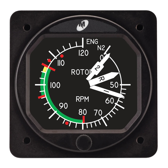
GENERAL DESCRIPTION INTRODUCTION The model MD23 series FLEX Custom Function Display (“CFD”) is a panel-mounted instrument capable of displaying various inputs in a configurable graphical presentation. FLEX is an off-the- shelf solution that is FAA and EASA TSO-approved with Level A design assurance software certification. -
Page 6: Technical Specifications
TECHNICAL SPECIFICATIONS Electrical Attributes Input Voltage: 10-32 VDC Input Power: 4 watts (0.14A @ 28VDC) Lighting Input: 5, 14, or 28VDC or automatic photocell control Battery Backup: (memory only) (1) Rechargeable coin cell Table 1.1 Data Inputs and Outputs 0-27.5VDC, ±0.050V accuracy, input impedance >50Kohms Analog... -
Page 7: Section 2 Pre-Installation Considerations
SECTION 2 PRE-INSTALLATION CONSIDERATIONS COOLING No external cooling is required. The unit will generate some heat as a function of normal operation. Installation in an area that is exposed to extreme heat or restricted airflow can reduce the expected life of the product. Mounting the unit to a metal surface can help reduce the effects of temperature on the unit but is not required. -
Page 8: Modification
The conditions and tests for TSO approvals of this article are minimum performance standards. Those installing this article, on or in a specific type or class of aircraft, must determine that the aircraft installation conditions are within the TSO standards, specification of the article, and deviations as listed above. -
Page 9: Section 3 Installation Procedures
SECTION 3 INSTALLATION PROCEDURES GENERAL INFORMATION IMPORTANT: READ THIS ENTIRE SECTION PRIOR TO STARTING INSTALLATION! This section contains interconnect diagrams, mounting dimensions and other information pertaining to the installation of the MD23 FLEX Custom Function Display. After installation of cabling and before installation of the equipment, ensure that power is applied only to the pins specified in the interconnect diagram. - Page 10 3.3.2 CONNECTOR PINOUT The supplied connector and backshell is required for proper installation and operation of the unit. The functions associated with the 26-pin high density D-subminiature connector are identified in Table 3.1 below. Note that for the -1 Indicator version of the unit (non-pitot/static), six of the MIO pins have different capabilities.
- Page 11 3.3.3 CABLE HARNESS ASSEMBLY To assemble the aircraft cable harness, refer to the following instructions and Figure 3.2: Install a pin/socket as supplied in the Connector Kit using an appropriate crimping tool for each wire in the aircraft cable harness. Be sure to make the harness long enough to remove the unit from the panel without stressing the harness.
- Page 12 Cable Harness Kit Parts Item Qty Description DSub, 26pin HD, with #22 contacts Backshell Backshell blanking plate Spring Clip Slide Lock Screw, Pan-head Phillips Cable Clamp Screw, Flat-head Phillips, Long Backshell Cover Screw, Flat-head Phillips, Short shields Figure 3.2 Mating Cable Harness Assembly Manual Number 9019161 Revision A, September 9, 2020...
-
Page 13: Pneumatic Pressure Connections
PNEUMATIC PRESSURE CONNECTIONS For the MD23 versions with pneumatic inputs, the connector kit supplied with the unit contains two (2) pneumatic quick disconnect fittings. These fittings are specific to the connections on the rear of the unit and are required for proper operation. The two fittings are marked with “S” and “P” on the case. -
Page 14: Installation Completion
INSTALLATION COMPLETION Prior to operating the unit in the aircraft, verify the basic operation of the unit and conduct a standard leak check of the pitot/static system per the aircraft maintenance manual or industry practice. Verify the proper CID number is installed for the application. Unit Versions Part Number Pneumatic Inputs... - Page 15 Figure 3.4 Panel Cutout Manual Number 9019161 Revision A, September 9, 2020...
-
Page 16: Section 4 Operation
SECTION 4 OPERATION IMPORTANT: READ THIS ENTIRE SECTION PRIOR TO OPERATING THE UNIT IN FLIGHT! The MD23 FLEX Custom Function Display is a unique new type of avionics equipment with a Patent Pending software concept. It utilizes a highly capable and certified hardware and software platform that can be customized to receive, output, and display a wide array of information. -
Page 17: User Interface
Power On Config Hold Introduction Menu Knob Screen PRE-FLIGHT MODE Normal Operation Hold User Config Options Menu Knob Menu* User Options Menu* CONFIG MODE FLIGHT MODE Figure 4.1 System Navigation Map USER INTERFACE The MD23 FLEX CFD is designed for simple, intuitive operation for ease of use for all custom applications. -
Page 18: Pre-Flight Mode
4.2.2 MENU OPERATION The menu parts are defined below: Menu title white text on a blue background at the top of each menu Current item cursor highlighted by a white box and green background Selectable items any selectable item on the menu is indicated with white text Unavailable items information only / unavailable options are indicated with gray text Menu operation throughout the MD23 is simple and intuitive:... -
Page 19: Flight Mode
FLIGHT MODE In Flight Mode, the unit operates normally according to the function of the CID and displays the primary graphical presentation. Operational details of specific custom applications are provided separately as a User Guide that serves as a compliment to this manual. The Options Menu, with manual brightness adjustment and the User Options Menu, is accessible in Flight Mode. - Page 20 4.4.1.1 BRIGHTNESS The display brightness can be controlled with either an external voltage or automatically using the integrated photocell. See Section 4.4 for further details. The Brightness feature in the Options Menu allows the user to manually adjust or offset the display brightness up or down regardless of the current level set by the External or Internal (automatic) brightness control method.
- Page 21 4.4.1.3 INFO While in Flight Mode, the Info menu is available to the pilot or cockpit crewmembers. It offers read-only information regarding the current software version and CID version. Pressing the Control Knob will revert to the active display. (Figure 4.5) Figure 4.5 Info Menu 4.4.1.4 EXIT The Exit action allows the user to manually close the Options Menu and return to the active...
-
Page 22: Configuration Mode
CONFIGURATION MODE Configuration Mode is used by the installer to configure aircraft specific requirements that are not accessible in flight. This includes critical flight parameters that contribute to the safe and certified operation of the unit and the aircraft as well as user preferences. Several safeguards are in place to prevent a user from ever accessing the Configuration Mode while in flight. - Page 23 4.5.1.1 DIMMING CONTROL The Dimming Control setting allows the installer to select the source of dimming control. It can be an “EXTERNAL” source, typically the aircraft’s adjustable lighting bus, or it can use the integrated photocell built into the unit (“INTERNAL” option) which senses the ambient light conditions and adjusts the display brightness/dimming automatically.
- Page 24 4.5.1.2 DIMMING CURVE The Dimming Curve feature allows the installer to customize the response to the Dimming Control input, whether Internal or External, over its range of operation. To do this, a desired brightness can be assigned for multiple points across the input range to produce a unique dimming scheme that most closely matches the other instruments in the panel and the pilot’s preferences.
- Page 25 Dimming Curve (continued) The best method for setting the dimming curve is to simulate the range of lighting conditions while adjusting the display brightness. This is best done after installation, in the actual aircraft instrument panel, but can be simulated in various environments. Dimming Curve Programming Process: (after selecting the Dimming Curve menu item) 1.
- Page 26 4.5.2 UPDATE The Update action initiates a search on an USB flash drive installed in the USB Program Port on the rear of the unit. (Figure 3.3) Step-by-step instructions on performing an update can be found in Section 5. The unit will search for a standard file name on the USB flash drive that represents either the unit operating software or a CID file.
- Page 27 4.5.3 USER CONFIGURATION The User Configuration Menu provides selectable options associated with the loaded CID that are intended to be configured during installation. It is only available and active if the specific design of the CID includes it (and gray/unavailable otherwise). See the applicable User Guide associated with the loaded CID for specific details.
-
Page 28: Section 5 Conformance
SECTION 5 CONFORMANCE INSTRUCTIONS FOR CONTINUED AIRWORTHINESS 5.1.1 PRESSURE SYSTEM VERIFICATION If the MD23 is configured to accept and display data associated with a static, pitot, or other pressure source, some aviation regulations may apply to inspect and test for accuracy on a regular basis. - Page 29 PREPARATION 1. Download the approved software and/or CID file to the root directory of a standard FAT- formatted USB flash drive. The downloaded file must retain the exact file name. 2. Ensure that the unit is powered off. 3. Remove the unit from the instrument panel. a.
-
Page 30: Environamental Qualification Statement
ENVIRONAMENTAL QUALIFICATION STATEMENT MODEL NUMBER: MD23 Series PART NUMBER: 6420023-( ) DESCRIPTION: 2-inch Custom Functional Display CERTIFICATION: FAA TSO-C2d (Type B), C10c, C106, C113b MANUFACTURER: Mid-Continent Instrument Co., Inc. ADDRESS: 9400 E. 34 St. North, Wichita, KS 67226, USA SPECIFICATION:...
Need help?
Do you have a question about the MD23 Series and is the answer not in the manual?
Questions and answers