
Summary of Contents for YOKOGAWA YEWSERIES 80 SDBS (Style S)
- Page 1 User’s Manual Model SDBS (Style S) Distributor IM 01B04T02-02E 14th Edition Y okogawa Electric Corporation...
-
Page 3: Table Of Contents
Contents Chapter 1 Introduction Inspection ..........................1-2 Documentation Conventions ....................1-3 Notice ..........................1-4 Chapter 2 General Standard Specifications ......................2-2 Model and Suffix Codes ......................2-3 Chapter 3 Installation External Wiring ........................3-2 Chapter 4 Principle of Operation Chapter 5 Operation Names of Components .......................5-2 Pre-operational Checks .......................5-3 Chapter 6 Maintenance... - Page 4 Blank...
-
Page 5: Chapter 1 Introduction
Chapter 1 Introduction Introduction This manual describes the functions and operations of the SDBS Distributor. ● Intended Readers This manual is intended for personnel in charge: • Installation and wiring • Instrumentation and setup of the function • Operation and monitoring of the controller •... -
Page 6: Inspection
Check the package contents against the list below. If anything is missing or damaged, immediately contact the sales office from which you purchased the product or your nearest Yokogawa representative. • SDBS Distributor ....................1 • Precautions on the Use of the YS80 Series ............1... -
Page 7: Documentation Conventions
The product has a QR Code pasted for efficient plant maintenance work and asset information management. It enables confirming the specifications of purchased products and user’s manuals. For more details, please refer to the following URL. https://www.yokogawa.com/qr-code QR Code is a registered trademark of DENSO WAVE INCORPORATED. IM 01B04T02-02E... -
Page 8: Notice
• Yokogawa does not make any warranties regarding the product except those mentioned in the WARRANTY that is provided separately. • Yokogawa assumes no liability to any party for any loss or damage, direct or indirect, caused by the use or any unpredictable defect of the product. -
Page 9: Chapter 2 General
Chapter 2 General General SDBS distributor is both designed to supply operating power to two-wire type transmitters and convert 4 to 20 mA DC current signal from these transmitters into output signals. SDBS distributor is designed for four inputs and is available in a loop isolation type. SDBS distributor have built-in current limiters allowing normal operation even when a short- circuit occurs on the transmitter side. -
Page 10: Standard Specifications
Standard Specifications Please see the General Specifications (GS 01B04T02-02E) at the end of this manual. IM 01B04T02-02E... -
Page 11: Model And Suffix Codes
Model and Suffix Codes Model Suffix Codes Option Codes Description SDBS Distributor Isolation, Inputs -14 Loop isolation, four inputs Suffix Codes Always 0 Style Code Style S (*1) (*2) Option Codes /NHR Without rack case /FBP Power supply fuse bypass /LOCK Power supply plug with lock /WSW... - Page 12 Blank...
-
Page 13: App
Chapter 3 Installation Installation For details of the installation procedure and wiring precautions, refer to instruction manual “Installation of Rack-Mounted Instruments” (IM 1B4F2-01E). IM 01B04T02-02E... -
Page 14: External Wiring
External Wiring (a) To prepare cables for connection to each terminal, install crimp-on solderless lugs for 4 mm screw on the end of each cable. (b) Draw the internal unit out from the rack case. (c) Connect the cables to the correct terminals by referring to Table 3-1. (d) Replace the internal unit into the rack case after completing the wiring. -
Page 15: Chapter 4 Principle Of Operation
Chapter 4 Principle of Operation Principle of Operation The SDBS supplies power to a two-wire type transmitter through the current limiter CL and converts a 4 to 20 mA output current signal from the transmitter into a 1 to 5 V DC signal. CL prevents excessibe current if a short-curcuit occurs in the field wiring. - Page 16 Blank...
-
Page 17: Operation
Chapter 5 Operation Operation Once the installation and wiring are completed, this distributor can be placed in operation by simply turning on the power switch. This distributor does not require any adjustments, but the inspection and checks described in Section 5-2 should be made before the unit is placed in operation. -
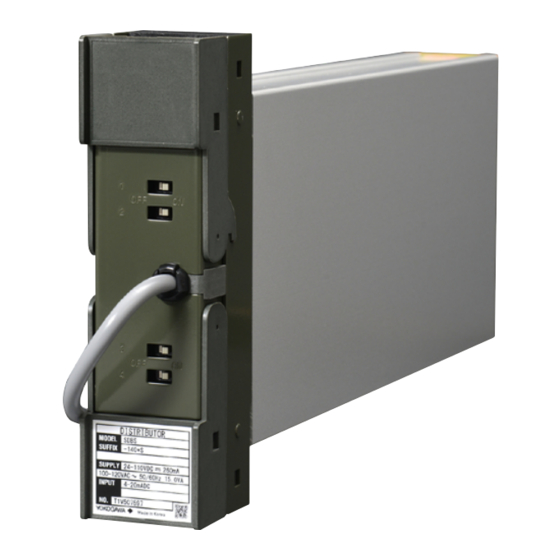
Page 18: Names Of Components
Names of Components Tag plate ON / OFF power switch for transmitter Nameplate D I S T R I B U T O SD BS -1 40 *S 24 -1 10 10 0- 12 VD C 0V AC 26 0m A 50 /6 0H 4- 20 mA 15 .0 VA... -
Page 19: Pre-Operational Checks
Pre-operational Checks Inspect and check the following points before entering the unit into normal operation. (1) Draw the internal unit out from the rack case and insure that the specified fuse is installed in the fuse holder at the back of the internal unit. (2) Before sliding the internal unit back into the rack case, check that the rack case connector is securely connected to the internal unit. - Page 20 Blank...
-
Page 21: Maintenance
Chapter 6 Maintenance Maintenance This chapter deals with simple maintenance procedures and parts replacements. IM 01B04T02-02E... -
Page 22: Test Equipment
Test Equipment For efficient maintenance of this distributor, the user is advised to have the following test equipment manufactured by YOKOGAWA or its equivalents before the need for maintenance arises. ● Voltage/current standard, Yokogawa GS200 or the equivalent ..1 set ● Digital voltmeter, Yokogawa DM7560 or the equivalent ....1 set... -
Page 23: Calibration
Table 6-1. Input/Output Characteristics Input Output 4 mA 1 ± 0.008 V 8 mA 2 ± 0.008 V 12 mA 3 ± 0.008 V 16 mA 4 ± 0.008 V 20 mA 5 ± 0.008 V Yokogawa DM7560 or Circuit Standard Voltmeter the equivalent – Number Connector Terminal + – Digital voltmeter Hi – Lo 1 – 2 A –... -
Page 24: List Of Replaceble Parts
List of Replaceble Parts Contact YOKOGAWA’s sales office or sales representative when replacing the spare parts. Part Name Part Number Recommended Reference replacement period Fuse S9510VK Approx. 3 years If the fuse breaks or if the replacement period elapses, please have the item replaced. -
Page 25: Chapter 7 Troubleshooting
If any fault occurs in the instrument, note the symptoms. To find the fault, first wire the instruments according to Figure 6-1, apply an input signal, and check the details of the error. If the fault is difficult to find, contact your nearest Yokogawa sales staff. IM 01B04T02-02E... - Page 26 Blank...
-
Page 27: Chapter 8 Power Supply Terminal Connections (Options /Tb, /A2Tb, And /Rek)
Chapter 8 Power Supply Terminal Connections (Options /TB, /A2TB, and /REK) Power Supply Terminal Connections (Options /TB, /A2TB, and /REK) If you specify the terminal block to which the power source is directly connected (option codes: /TB, /A2TB, and /REK), the external wiring to the terminal block is necessary; therefore, drawing out the internal unit requires previous turning off of the power source and disconnection of the wiring from the terminal block. -
Page 28: External View And Names Of Components
External View and Names of Components Output Terminal Block Output Terminal Cover Power Fuse Power Terminal Cover Input Terminal Block Power Terminal Power and Ground Terminal connection (Connection screw: M4) Symbol Description Input Terminal Cover + Power supply Ground Figure 8-1 External View and Names of Components IM 01B04T02-02E... -
Page 29: Power Supply And Ground Wiring
Power Supply and Ground Wiring (1) All cable ends must be furnished with crimp-on type solderless lugs (for 4 mm screw). (2) Examples of applicable cables: Cross-sectional area of the cable conductor: 2.0 mm Applicable cable: 600 V vinyle insulated cable (IV) stranded wires, conforming to JIS C3307. - Page 30 Blank...
-
Page 31: General Specifications
General Model SDBS (Style S) Specifications Distributor GS 01B04T02-02E n GENERAL The Model SDBS Distributor supplies power to a two-wire transmitter and converts the 4 to 20 mA DC transmitter signal current to two 1 to 5 V DC output signals. - Page 32 Do not connect to the output terminal when the terminal is not in use. Terminal Description Designation Transmitter 1 (Input 1) Transmitter 3 (Input 3) Transmitter 2 (Input 2) Transmitter 4 (Input 4) All Rights Reserved. Copyright © 2002, Yokogawa Electric Corporation GS 01B04T02-02E Sep.17, 2019-00...
- Page 33 Symbol Description + Power supply Ground Trigonometry Unit: mm General tolerance = ±(value of tolerance class IT18 based on JIS B 0401-2016) / 2 F02.ai All Rights Reserved. Copyright © 2002, Yokogawa Electric Corporation GS 01B04T02-02E Sep.17, 2019-00...
- Page 34 (Connection screw: M4) Symbol Description + Power supply Ground Trigonometry Unit: mm General tolerance = ±(value of tolerance class IT18 based on JIS B 0401-2016) / 2 F03.ai All Rights Reserved. Copyright © 2002, Yokogawa Electric Corporation GS 01B04T02-02E Sep.17, 2019-00...
- Page 35 *2: /FBP, /A2TB, and /A2ER cannot be specified together. n ORDERING INSTRUCTIONS Specify the following when ordering: Model and suffix codes and option codes, if necessary. All Rights Reserved. Copyright © 2002, Yokogawa Electric Corporation GS 01B04T02-02E Sep.17, 2019-00 Subject to change without notice.
- Page 36 Blank...
- Page 37 : IM 01B04T02-02E 12th Edition/July 2002 Renewal 13th Edition/May 2004 Change of the company name. 14th Edition/Oct. 2019 Change of the style number. n Written by Yokogawa Electric Corporation n Published by Yokogawa Electric Corporation 2-9-32 Nakacho, Musashino-shi, Tokyo 180-8750, JAPAN...
- Page 38 3F Tower D Cartelo Crocodile Building, No.568 West Tianshan Road, Shanghai 200335, CHINA Phone : 86-21-62396262 Fax : 86-21-62387866 YOKOGAWA ELECTRIC KOREA CO., LTD. (Yokogawa B/D, Yangpyeong-dong 4-Ga), 21, Seonyu-ro 45-gil, Yeongdeungpo-gu, Seoul, 07209, KOREA Phone : 82-2-2628-6000 Fax : 82-2-2628-6400 YOKOGAWA ENGINEERING ASIA PTE. LTD.
Need help?
Do you have a question about the YEWSERIES 80 SDBS (Style S) and is the answer not in the manual?
Questions and answers