
Summary of Contents for Nivetec NIVOCONT
- Page 1 NIVOCONT VIBRATING ROD LEVEL SWITCHES USER’S MANUAL BKI16ATEX0005 rkh5021m0600h_06 1 / 16...
- Page 2 APPROVALS: BKI ATEX, Certificate No.: BKI16ATEX0005 BKI IECEx, Certificate No.: IECEx BKI 13.0001x issue No.: 0 2 / 16 BKI16ATEX0005 rkh5021m0600h_06...
-
Page 3: Table Of Contents
CONTENTS 1. INTRODUCTION ........................................5 2. ORDER CODES ........................................5 2.1 Accessories ............................................... 5 3. TECHNICAL DATA ....................................... 6 3.1 General specification ..........................................6 3.2 Dimensions ..............................................7 3.3 Additional data for explosion-proof devices ....................................8 ... - Page 4 4 / 16 BKI16ATEX0005 rkh5021m0600h_06...
-
Page 5: Introduction
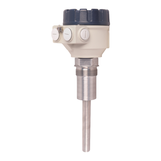
We are sure that you will be satisfied throughout its use. 1. INTRODUCTION The NIVOCONT vibrating rod level switches are suitable for low and high level indication of granules and powders with a min. 0.05 kg/dm density such as cement, lime, sand, grain, feed, sugar, etc. -
Page 6: Technical Data
3. TECHNICAL DATA 3.1 General specification ERSION TANDARD IPE EXTENDED ABLE EXTENDED USTOM EXTENDED Probe length 207 mm [8.15 in] 0,3 – 3 m [0.98 – 9.84 ft] 1 – 20 m [3.28 – 65.62 ft] 0,2 – 2m [0.66 – 6.56 ft] Material of wetted parts 1.4571 rezgő... -
Page 7: Dimensions
EMPERATURE DIAGRAM [°C] 100 110 160 T [°C] Figure 2. F = 500 N M = 100 Nm Ambient temperature (T ) versus medium temperature (T M = 100 Nm F = 45 kN 3.2 Dimensions STANDARD PIPE EXTENDED CABLE EXTENDED CUSTOM EXTENDED Figure 3. -
Page 8: Additional Data For Explosion-Proof Devices
3.3 Additional data for explosion-proof devices 3.3.1 ATEX Approval, No. BKI16ATEX0005 RK-5-5E , RH-5-5E , RS-5-5E , RT-5-5E Ex marking II1/2 D Ex ta/tb IIIC T90 °C…T170 °C Da/Db Supply voltage (universal) 20 – 250 V AC (50 / 60 Hz) or 20 – 50 V DC 2 pcs. -
Page 9: Iecex Approval No. Iecex Bki 13.0001 X
3.3.2 IECEx Approval No. IECEX BKI 13.0001 X RK-5-5E RH-5-5E RS-5-5E RT-5-5E TYPE Ex MARKING Ex t IIIC T* Da/Db IP67 *(see Temperature data table) Supply voltage (universal) 20 – 250 V AC (50 / 60 Hz) or 20 – 50V DC 2 pcs. -
Page 10: Mounting
4. MOUNTING Prior to installation, it is advised to check the switching function for proper adjustment on a sample quantity of material (see: Installation). The unit may not work with mediums within the specified density range but having very large size of granules or extremely little friction. WARNING! Handle the device with great care, especially the sensing probe. -
Page 11: Installation, Putting Into Operation
Figure 5. Figure 6. 5. INSTALLATION, PUTTING INTO OPERATION Remove the top cover of the housing to access the connection terminals and adjusting switches. In case of Dust Ex instruments the housing cover can be only opened after the removal of the socket cap screw fixed safety locking bolt. -
Page 12: Wiring
6. WIRING Status LED Status LED Overload LED 250VAC 8A/AC1 350mA N L1 2,7k 1 2 3 4 5 6 N L1 1 2 3 4 5 6 +24V NO C NC N L1 Figure 7. Figure 8. Wiring of relay output version Wiring of optocoupled sink input to solid state ouput version supplied from a AC line Status LED Status LED... -
Page 13: Operation Diagram
6.1 Operation diagram POWER PROBE FAIL-SAFE MODE RELAY SOLID STATE OUTPUT 2,7 k GREEN ENERGISED NOT VIBRATING (COVERED) 2,7 k HIGH DE-ENERGISED 2,7 k DE-ENERGISED VIBRATING (FREE) 2,7 k HIGH GREEN ENERGISED 2,7 k FAILS NOT LIT HIGH DE-ENERGISED ... -
Page 14: Mounting Of Custom Extended Type
7. MOUNTING OF CUSTOM EXTENDED TYPE Attention! The device must not be installed with the temporary (plastic) extension pipe! Remove the temporary (plastic) extension pipe. Cut a 1" inch stainless steel (1.4571) extension pipe to the desired length. (Not part of the package.) ... - Page 15 BKI16ATEX0005 rkh5021m0600h_06 15 / 16...
- Page 16 rkh5021a0600h_08 August 2018 16 / 16 BKI16ATEX0005 rkh5021m0600h_06...
Need help?
Do you have a question about the NIVOCONT and is the answer not in the manual?
Questions and answers